The mystery of clay – professional exploration of deposits
 Photo/Foto: Krakow, by courtesy of/mit freundlicher Genehmigung THADE GERDES GmbH (2019)
 Photo/Foto: Krakow (2008)
 Photo/Foto: Krakow (1987)
 Picture/Bild: redrawn from/umgezeichnet aus [1]
 Photo/Foto: Krakow (1985)
 Photo/Foto: Krakow, by courtesy of/mit freundlicher Genehmigung Gerdes GmbH (2019)
 Photo/Foto: Krakow, by courtesy of/mit freundlicher Genehmigung Thade Gerdes GmbH (2019)
 Picture/Bild: redrawn from/umgezeichnet aus [2]
 Picture/Bild: redrawn from/umgezeichnet aus [2]
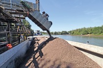
 Photo/Foto: Krakow, by courtesy of/mit freundlicher Genehmigung Celler Brunnenbau GmbH (2008)
 Photo/Foto: Krakow, by courtesy of/mit freundlicher Genehmigung Celler Brunnenbau GmbH (2008)
 Photo/Foto: Krakow, by courtesy of/mit freundlicher Genehmigung Celler Brunnenbau GmbH (1996)
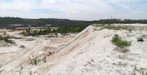
 Photo/Foto: Krakow (2020)
 Photo/Foto: Krakow (2017)
 Photo/Foto: Krakow (2017)
Geological exploration is the first step in a complex value creation chain ending in the brick plant with the production of high-quality products. Not only the most important exploration methods depending on the expected type of resource are described in detail, typical exploration errors are also discussed.
1 Introduction
Just imagine that you have a wonderful new clay site: no housing construction, no rival uses, no FFH areas, and with no resistance from the local population against clay extraction expected either.
In this situation, you are always faced by the same questions:
Of what quality is the raw material?
What quantity is available?
Are there geological faults?
How many drillings are needed?
Where and in what grid pattern should boreholes be drilled?
How deep should the boreholes be drilled?
What drilling method should be chosen?
Can geophysical or geoelectric exploration methods be used? If yes, who can do that?
All these questions are reasonable, after all, from a geoscientific perspective, clays are one of the most complicated mixtures of minerals in the continental crust. In this context, the author likes to use the term “the mystery of clay“. Type and content of the submicroscopically small clay minerals crucially determine the ceramic-related properties. And it is imperative that these sensitive parameters are not modified by unsuitable drilling and sampling processes.
Another example are petrographic inhomogeneities/impurities within the clay sequence, for example sandstone layers, dolostone beds or clumps of gypsum, typically from the cyclic playa sequences from the Rotliegend, Zechstein, Buntsandstein and Keuper – alternating sequences, the clean exploration of which requires highly sophisticated drilling technology.
An old saying says that mistakes make you smarter, that is why one is not enough. This article therefore addresses typical exploration errors that have been made in the past, but which are still repeatedly made today, usually owing to a lack of routine, partly, however, because of ignorance or excessive risk tolerance. The consequences range from the unnoticed through the curious to the serious.
2 Lacking geological exploration
The first mistake that can be made is that simply nothing is done at all – full risk, no exploration.
Old survey reports compiled decades earlier with a completely different objective are relied upon. The motto here is that everything will turn out fine. Millions are invested in plants and equipment. But clay extraction has hardly started before the nasty surprises start turning up. The supposed fantastic brick clay contains sand, limestone and organics – as has happened repeatedly in Brandenburg. Or a typical example from North Rhine-Westphalia: the sought-after clinker clay, only a few metres thick in any case, gradually sinks under mountains of overburden: a ten-year approval process, stone separation machine, clay body adjustment – all for nothing. Just to save money, one exposes oneself to a completely incalculable technical and therefore naturally high financial risk.
3 Blind activism
The second error goes precisely in the opposite direction. In the truest sense of the word, holes are made in the earth without any plan at all.
But you definitely need a plan, e.g. one with the most important supply lines underground: gas, power, telephone, water. Drilling into such lines can be very unpleasant and expensive. Moreover, a plan with plot boundaries is needed, otherwise holes may be drilled on the wrong plot (»2a). All of that has happened before, even in Germany.
Moreover an idea of the expected geological and hydrogeological conditions is needed. For that is the basic precondition for the choice of the right drilling method and contracting of the drilling work. That is also the basis for determining the initial drilling points and end depths. Knowledge of the hydrogeological situation protects against drilling into confined groundwater, which is generally associated with a lot of hassle and high costs (»2b).
4 Wrong exploration/drilling process
4.1 History
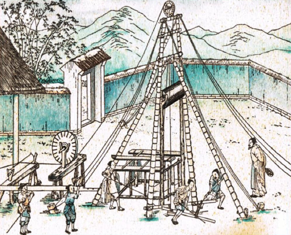
Back in the 13th century, drilling technology for accessing water, coal and other raw materials already existed in China.
The percussion drilling technology used is still practiced today in principle. With drilling diameters up to 300 mm, final depths of several 100 m were achieved. However, to sink such boreholes, up to ten years were needed (»3a). In historical documents from the time of the pharaohs in Egypt, traces of drilling work can be found [1]. Over the course of the centuries, drilling technology has been steadily further developed to improve the controllability of geological risks. Today a range of different exploration/drilling methods is available to optimally assess the viability of deposits (probability with which on account of the geological conditions, in comparison with known deposits, concentrations or deposits for certain mineral resources can be expected). Here the rule is: the denser the exploration grid, the lower the risk.
4.2 General requirements today
Drilling methods and drilling diameter are primarily oriented to the type and quality of the required resource samples.
Basically, drilling methods are preferable with which the drilled material is extracted without it being disturbed and with which an unbroken record of the stratigraphic sequence is guaranteed. In clays endangered by erosion as well as in overlying coherent unconsolidated sediments, therefore, only dry drilling methods should be applied. The boreholes should be tubed as drilling progresses so as to prevent material from the borehole falling into the sample material.
To avoid subsidence and environmental damage, the boreholes must be carefully backfilled on subsequent retraction of the tube. Especially when confined groundwater is encountered or it is necessary to drill through several groundwater levels, the hydraulic barrier effect of the original layers must be restored by means of backfilling with high-grade clay pieces or clay pellets. Other criteria that can be decisive in the choice of the boring method refer primarily to the strength and consistency of the underground. Classification and remuneration are usually based on soil classes 1 to 7 in accordance with DIN 18300. Crucial to the choice of the drilling method are the exploration depth, the groundwater conditions and the available cost framework.
In the exploration of brick clays, as a first step an exploration grid of 100 m x 100 m has proved effective. If the drilling results can be correlated well, the grid can be extended to 200 m x 200 m. If the results deviate on the other hand, densification of the grid to 50 m x 50 m can be recommended. If the picture still is not clear, then test diggings with a hydraulic excavator at 25 m x 25 m should be arranged. In solid rock sequences, however, the strike and dip of the beds should be taken into consideration. The following is generally the case: drilling in the line of strike opens up the same beds and usually yields in similar results. Drilling perpendicular to the strike covers different parts of the sequence, opening up the maximum range of materials in the raw material deposit.
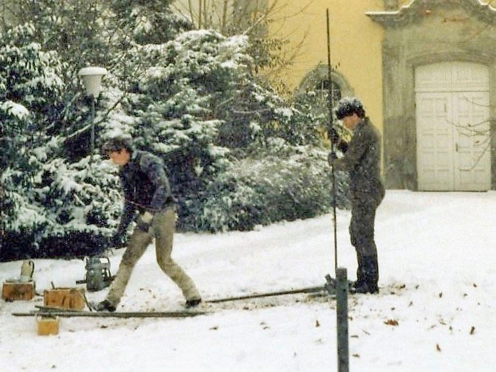
4.3 Probe drilling/small-scale drilling
Probe drillings with core diameters from 32 to 80 mm are classed as small-scale drilling, which can be sunk with the help of a motorized or electric handheld drill (»3b). A slotted probe is struck by the metre into the underground. Exploratory boreholes can only be sunk in geological formations of the classes 1 to 4 in accordance with DIN 18300, providing these exhibit a pappy, soft to a maximum of stiff consistency. This means for the brickmaker: clays cannot be explored on account of the high cohesive forces, however, it is effective for exploration of the loams and sands that often constitute the overburden of clay deposits. The achievable final depths depend on the penetration resistance in the underground. They measure around 6 to 12 m.
The essential advantage of probe drillings is that in soft layers small, but largely continuous and complete samples of the quality grades 2 to 3 can be obtained. There are also advantages in the limited ground disturbance, the good accessibility of the drilling points and in the comparatively low time/cost requirement. Especially in combination with core drilling, close-meshed exploratory drillings can generally be recommended, providing loam-like layers of low consistency and depth are to be explored.
4.4 Rotary drilling without mud circulation
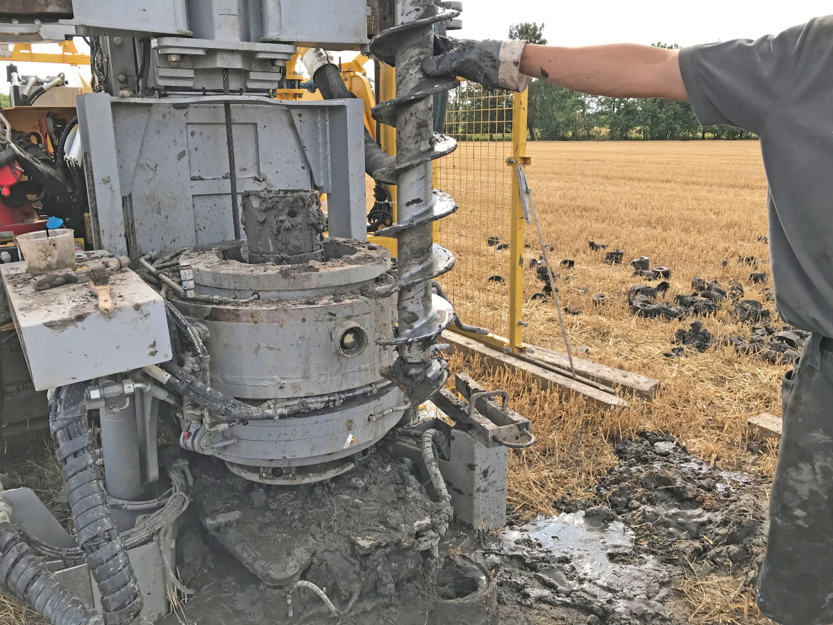
Drilling methods with an auger bit are suitable for unconsolidated rocks above groundwater level. Here a cylindrical auger loosens the underground with cutters or spiral heads. The casing picks up the disturbed drilled material. For better emptying, it is perforated. It is driven by means of a drill pipe turning and pressing. The sample quality generally corresponds to grades 3 to 4 and is therefore generally sufficient for an initial assessment of the raw material. The structural bond is disturbed. Important layer boundaries can, however, be identified.
Dry drilling methods with an auger are widely used in the exploration of cohesive loose rock such as loams and plastic clays and are relatively low cost. They can be used in geological formations of the classes 1 to 5 in accordance with DIN 18300. The achievable final depths mostly reach 30 to 40 m. The drilling auger loosens the underground with a cutting edge at the end of the spiral head (»4a). Then it is driven by a drill pipe turning and pressing. The sample material is compressed by the means of the drilling method, in line with grade classes 3 to 4 in accordance with DIN 4021. The structural bond is disturbed. Layer boundaries can be easily identified. Quality and quantity of the sample material are sufficient for a sound assessment of the resource (»4b). Modern plants have the option for removal of special samples of quality class 1 in accordance with DIN 4021.
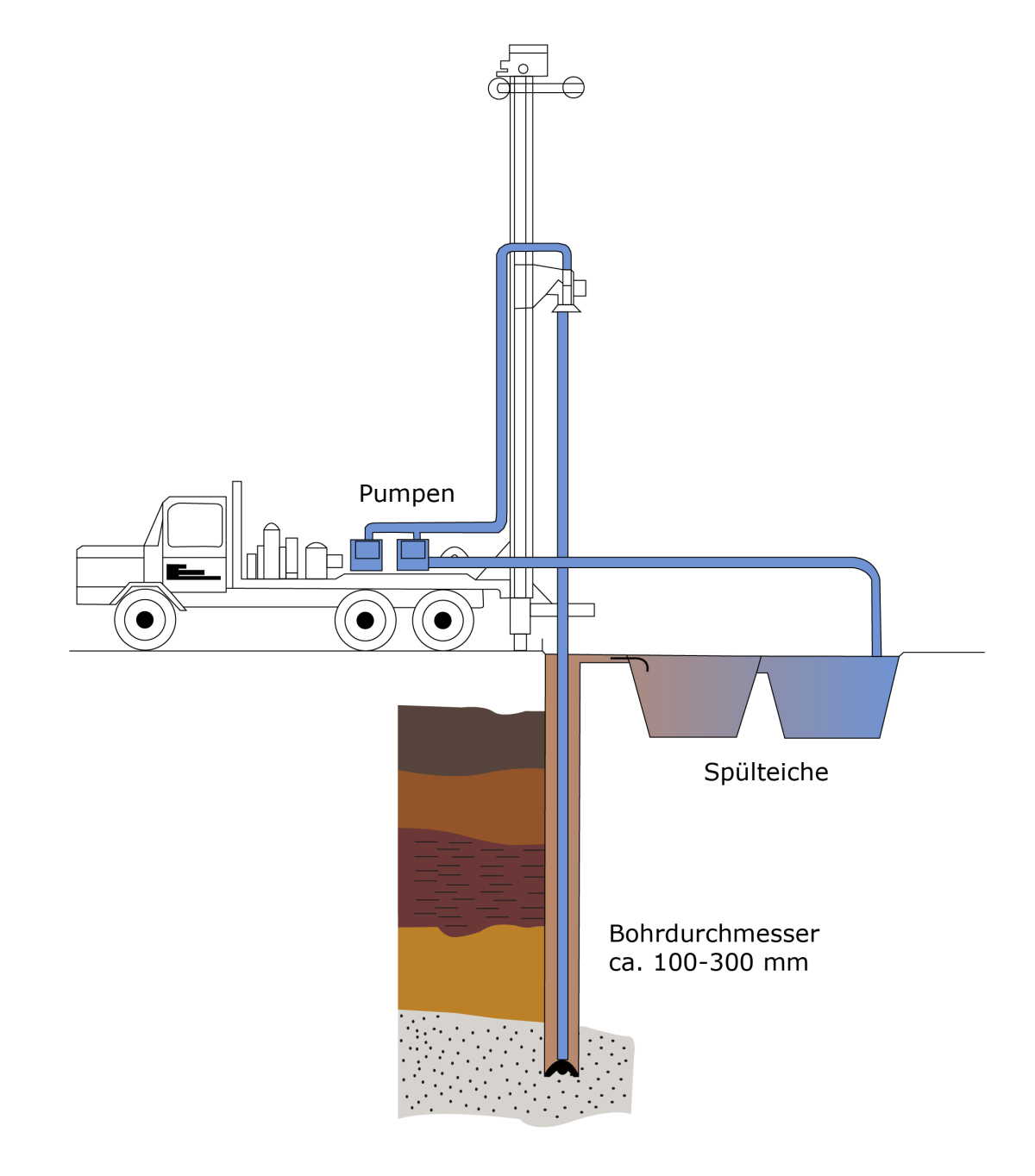
4.5 Mud rotary direct circulation drilling
For sinking deep exploration drilling in geological formations of the classes 1 to 7 (all unconsolidated and consolidated rocks) the mud rotary direct circulation drilling method is used. It is the commonly used method in the oil and natural gas industry and enables final depths of several thousand metres. In mud direct circulation drilling, the underground is first loosened from the bottom of the borehole by the rotary movements of the drilling tool (drag bit, roller bit) and then conveyed to the surface. For this, piston and centrifugal pumps are used to pump the mud from a mud pit through a delivery hose and through drilling tool to the bottom of the borehole. There the mud together with the drillings enters in the annular space between the borehole rod and the borehole wall and is conveyed above ground (»5).
In mud pits or mud tanks, the drilled material conveyed in the suspension settles and is available there for sampling. Through a suction hose, the clean mud with the solids removed is then recirculated. As with mud rotary direct circulation drilling only disturbed and primarily incomplete samples of quality class 5 in accordance with DIN 4021 can be obtained, and only from the required depth in certain circumstances, this method cannot be recommended for the clay brick and tile industry. To record important geological layer boundaries, supplementary physical measurements of the borehole would have to be performed. But as a result, the quality of samples would not be improved.
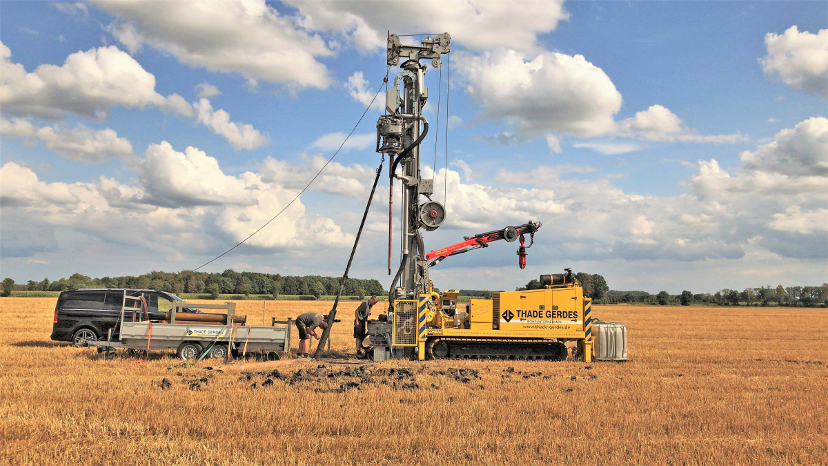
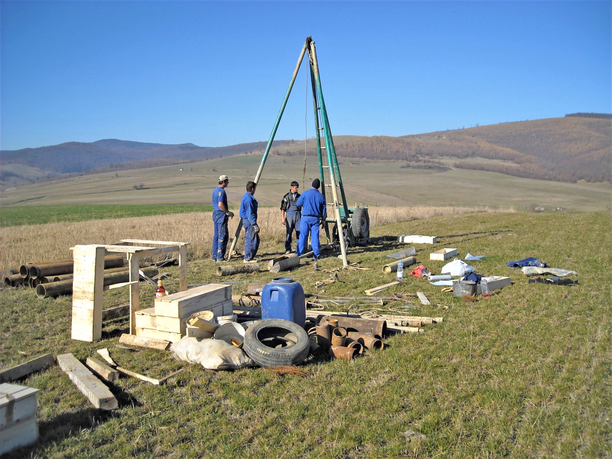
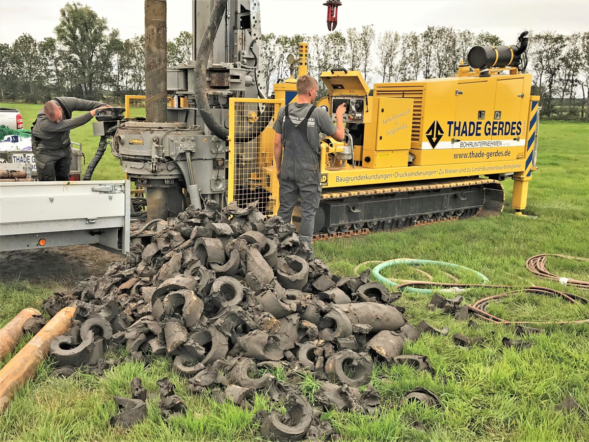
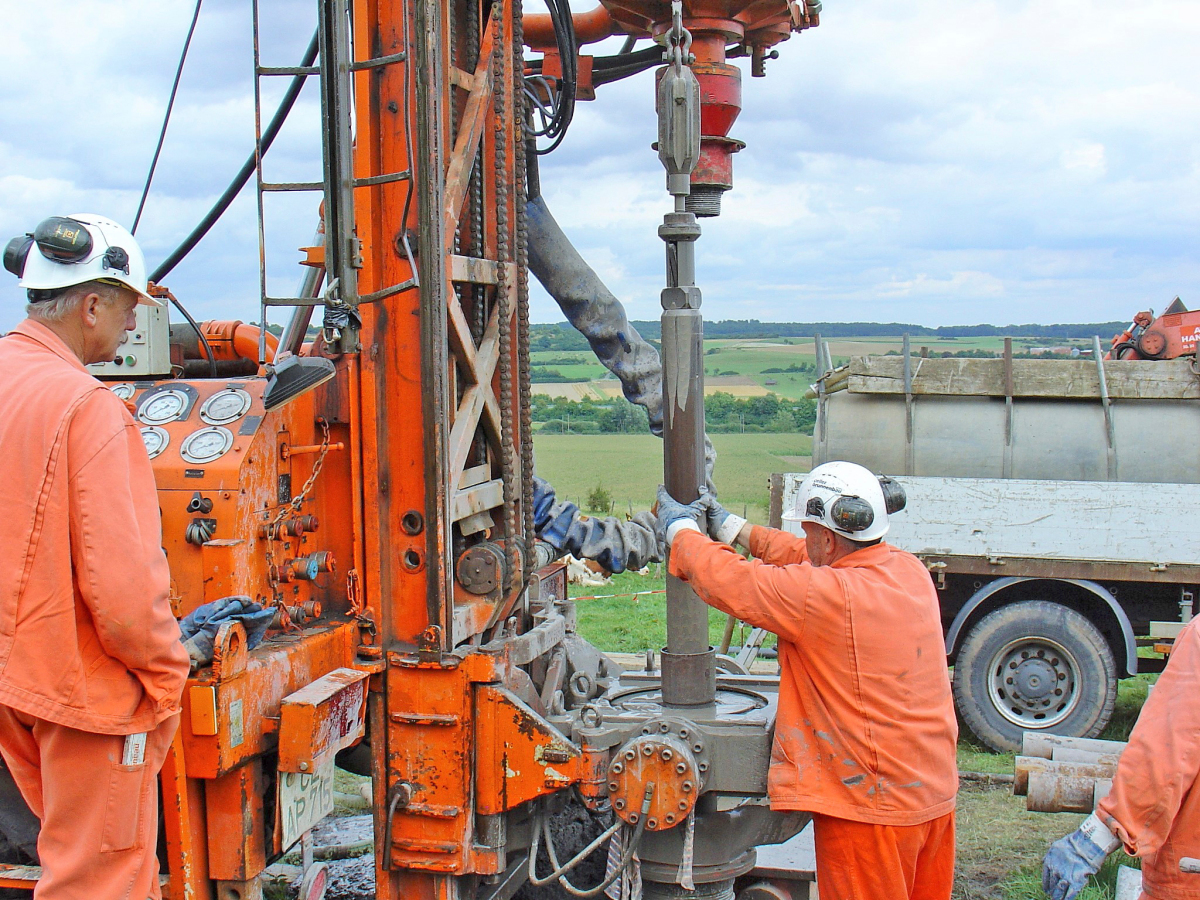
4.6 Ram core drilling methods
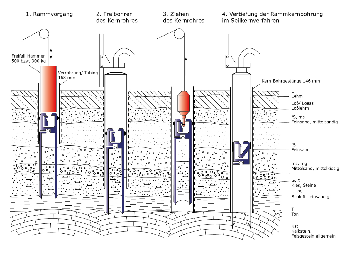
To obtain continuously undisturbed, complete and depth-appropriate resource samples from geological formations of the classes 1 to 5 in accordance with DIN 18300 (clay, silt, sand, gravel), the ram core drilling method is used effectively. First a 168-mm standpipe is positioned, and the ram core tube is fitted with a PVC inliner. Then the core barrel is rammed with a free-fall hammer into the underground. The ram strokes necessary for driving the barrel are recorded to obtain an indication of the strength of the underground (»6.1). The cored section in the PVC liner usually measures 1.0 m in length. When the core barrel has been completely rammed into the underground, after removal of the rams, the core pipe is drilled over with a 168-mm casing and the borehole wall secured in this way (»6.2). To pull the ram core barrel more easily and to protect the drilled core, overdrilling is usually performed with water as flushing aid.
Then the lifter is inserted into the borehole and connected with the core barrel. After this the ram core barrel is detached from the bottom of the borehole and pulled up by means of a cable winch (»6.3). A core lifter clip at the bottom end of the core barrel prevents the drilled core falling out during extraction. After the drilled core in the PVC inliner has been removed out of the core barrel, it is sealed airtight for later assessment and stored in a core box. A core diameter of 101 mm has generally proven effective because relatively large numbers of samples can be taken. Depending on the strength of the underground, drilling depths in excess of 100 m are possible.
4.7 Rotary wireline core drilling
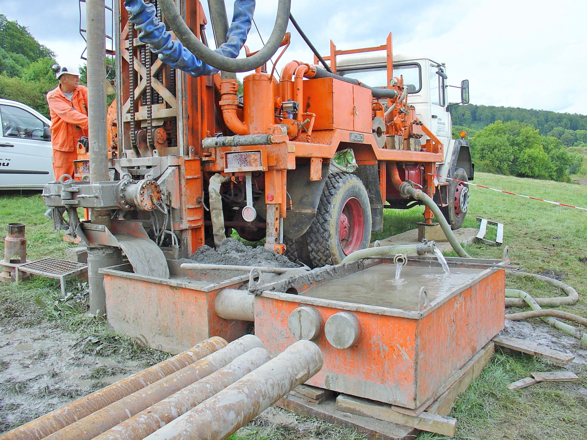
In solid rocks of the classes 6 to 7, cores are extracted by means of rotary circulation drilling. For the exploration of consolidated argillaceous rock sequences of every type (playa clay alternations, argillaceous rocks, shales, argillaceous schist, phyllite slate) the wireline core drilling method with double core barrel is easily the best exploration method (»7a). Above all, because sediment structures and the tectonic bedding conditions (inclination of the beds, joints, fissure mineralizations) can be effectively detected. The double core barrel offers the crucial advantage that during coring only the outer barrel rotates while the inner barrel does not rotate. As a result, the drilled core is not exposed to any permanent mechanical load. The generally common drilling diameter is 146 mm at a core diameter of 101 mm. A considerable advantage of this process is that it can be combined with the ram core drilling method. This means in practice: after drilling through the loose rock coverage, the ram core drilling can be easily deepened by means of the wireline core drilling method (»6.4).
With this drilling method, the mud is conveyed by means of piston pumps from a mud tank or a mud pit through the drill rod. Here the mud flows between the inside/outside barrels so that a constant hydraulic influence on the drilling core is avoided. Only in the area of the core bit where the mud stream leaves the interspace between the inner and outer pipes does the mud flow around the core for a short time over a length of around 10 cm. Key tasks of the mud are the cooling of the core bit, removal of drillings from the bottom of the borehole and stabilization of the borehole walls.
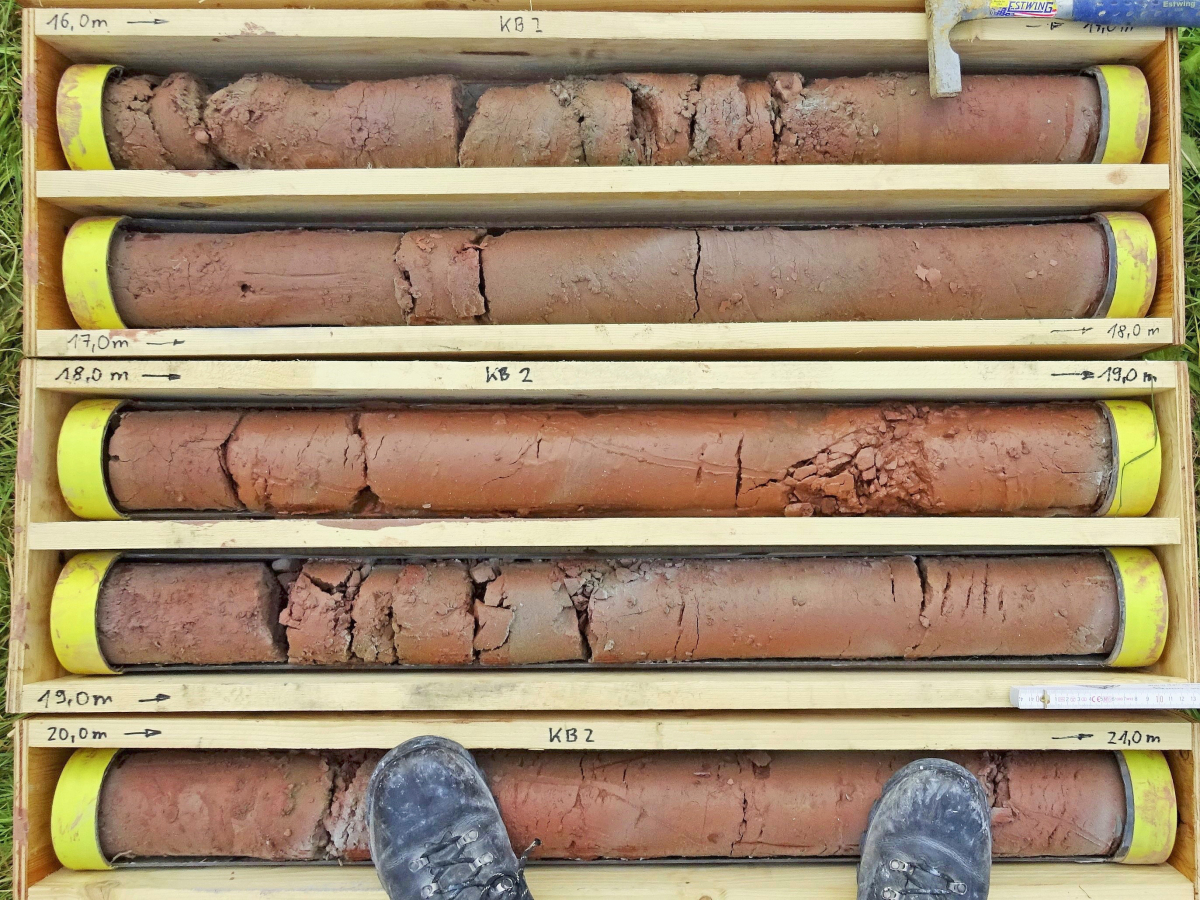
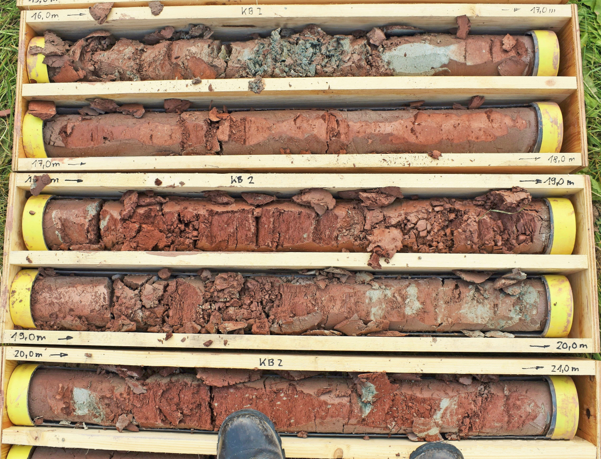
With this method, the cored section lengths measure 1.5 or 3.0 m as standard, in rare instances 6.0 or even 9.0 m. After completion of the coring process, the inner barrel with the core obtained is recovered with a cable winch while the drilling string with drilling bit remain in the borehole (»7b). After twisting off of the core lifter ring and careful removal of the core, the inner barrel can be reinserted into the borehole using the cable winch. Key precondition for an as complete as possible core removal is a good core preservation. Loose lumps of rock are not held by the core lifter clip, core losses result.
The core quality and the core recovery depend significantly on the choice of the right drill bit. In the exploration of heterogeneous argillaceous rock sequences, hard pin bits and Corborit-tipped bits can be recommended. In formations that are very difficult to core, here the use of PVC inliners can be recommended to additionally protect the core against the effects of mud circulation (»8a). With the rotary wireline drilling method, apart from the standpipe, uncased core drilling to several 100 metres are possible. The so far deepest vertical wireline core drilling reached a depth of 3500 m [1].
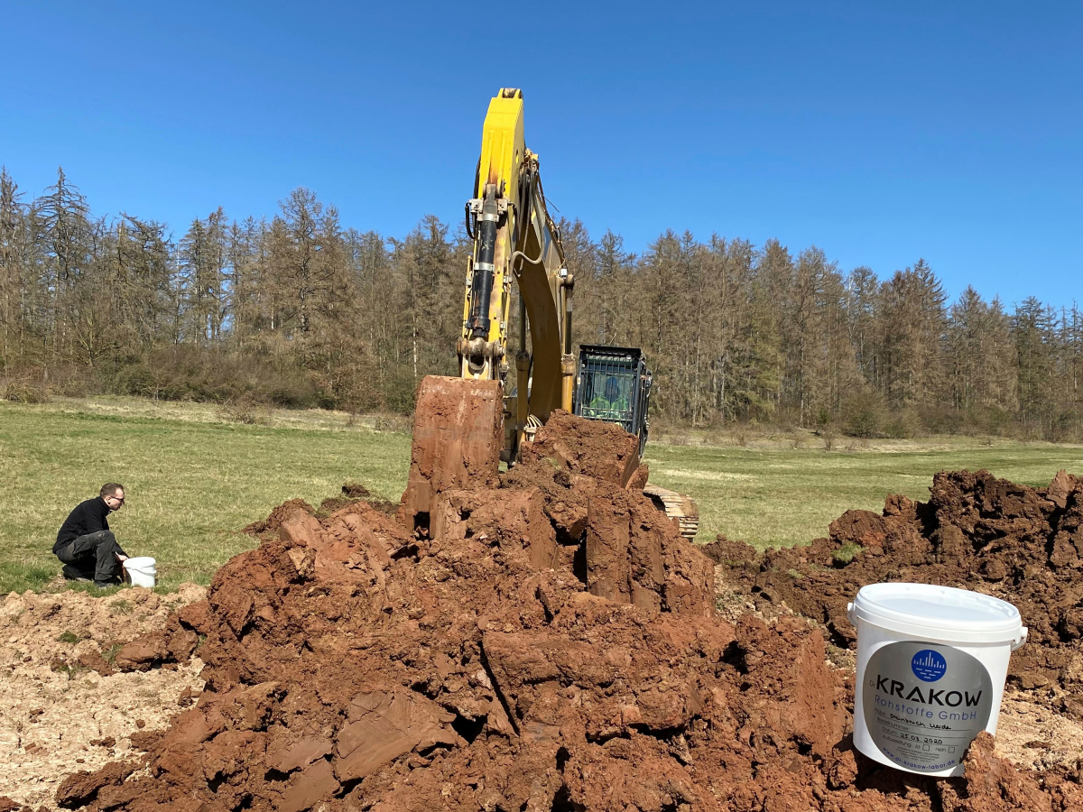
4.8 Exploratory pits with a hydraulic excavator
With the help of a hydraulic excavator with hoe attachment, geological formations of the classes 1 to 5 in accordance with DIN 18300 can be explored to depths to around 5.0 m below ground. Precondition is, however, that the beds to be explored lie above the groundwater level. The advantage lies primarily in the large-scale exploration geometry and the possibility to inspect these exploratory holes directly providing appropriate precautions are taken. So sediment structures can be described very well over their depth but also over their horizontal distribution and formation. For example, the inclination of the strata or the type and intensity of the joint structure. Another advantage is the possibility for removal of large sample quantities (»8b). Also the removal of special samples of quality class 1 in accordance with DIN 4021 is possible. Another advantage is the low time and cost expenditure. In a short time, many exploratory pits can be sunk, geologically logged and sampled.
A limitation besides the relatively small exploration depth is primarily the extent of ground disturbance. Irrespective of this, after logging, the prospecting pits must be closed carefully and in line with the horizon. Test digs with the excavator can be recommended primarily for densification of an exploration grid, especially for the exploration of overlying horizons.
4.9 Geophysical measurements
Geophysical measurements on the site surface are based methodically on the tracking of boundary surfaces based on different physical properties in the underground, like the propagation velocity of seismic waves or electrical resistance. Precondition is that the underground is built up only of two beds and that these beds differ clearly with regard to their wave velocities and their electrical resistance.
Advantages of the method are primarily the comprehensive exploration and the comparatively low financial expenditure. Limitations result from the necessary correlation of the measurement results with the results of direct exploration methods, generally with core drillings. Geophysical explorations can be recommended for densification of the exploration grid providing findings from direct explorations are positive. While main resource types like, for example, sand can be distinguished from clay, a distinction between different clay grades is not possible. Moreover, no samples can be extracted.
5 Incorrect geological information
The next exploration error is related less to the choice of drilling method but rather the result of inaccurate geological identification of the drilled material. Generally, it should first be noted that only few geoscience graduates are currently able to accurately describe unconsolidated and consolidated rocks. Everyone is talking about resource efficiency but hardly anyone can describe resources in geologic terms, never mind assess them. A common error is made in processing of the drilling cores.
What you have to know here: In the exploration of clayey sequences, especially with the help of mud, the surface of the drilled cores is covered by a mm-thin clay film (»9a). That means that this clay film must be removed before logging any details of the cores. Otherwise petrographic inhomogeneities/impurities and important sediment structures like the joint structures, thin bed boundaries and secondary mineralizations are not identified (»9b). It should be noted that exploration boreholes should always be logged with the necessary ceramic expertise. That is not a job for geotechnical engineering offices.
6 No deposit certification
Another error often lies in the inadequate documentation of the drilling results. Deposit exploration measures are generally associated with high financial expenditure and risk. For this reason, all work findings should be carefully documented. To this end, all exploration points and sampling points should be georeferenced and plotted. This includes in every case site plans, drilling graphs and geological profile sections and, if possible, also geological maps, isolines and isopach maps. In the text section, the geological structure of the deposit should be described in generally understandable language. This includes primarily the description of the geological transect with details on bed thicknesses, but also information on any encountered groundwater or geological fault zones.
For compilation of the deposit certification required by the authorities, visual results of the field work must be underpinned with qualified laboratory tests. It must be proven that the explored deposit must be available in sufficient quality and quantity. To this end, at least the following laboratory tests should be conducted on a representative number of samples:
Natural water content/pit moisture (DIN 18121)
Consistency limits after Atterberg (DIN 18122)
Particle size distribution in the screening/washing process (DIN18123)
Microscopy of the screen oversize >125 µm
Lime content of the screen oversize >125 µm
Ceramic-related characteristics (DKG directives)
Chemical composition (XRF)
Content of organically bound carbon (TOC)
Mineral composition (XRD/FTIR)
Simultaneous thermal analysis (STA)
Within the framework of the integrated ceramics suitability test, it must be reasonably shown that the explored deposit is in actual fact suitable for the planned application. On the basis of the laboratory tests, the samples taken must be classified as recoverable rock or overburden.
A widely held view is that the geological conditions do not change as a result of geological exploration. While this is correct, it is not relevant. Relevant is that the brick plants are given planning reliability and time to develop new resource strategies. That is the true purpose of geological exploration.