



Influence of internal atmosphere circulation on the temperature development with electrical heating elements
![» Figure 1: Temperature profiles along the tunnel kiln (natural gas) recorded with thermocouples in the setting [2]](https://www.zi-online.info/imgs/2/4/2/1/7/2/5/Abbildung_1_neu-9d72ac2f1a6b3ba8.jpeg)


1 Introduction
In Germany, the brick and tile industry emits about 1.73 million tons of CO2 per year [1]. More than 56% of this emission is due to the use of natural gas for the drying and firing process in the entire manufacturing chain. In the brick and tile industry, the firing process is carried out in a tunnel kiln. Electrification of the tunnel kiln process has been considered as an alternative to the use of hydrogen or ammonia due to factors ranging from price and availability to avoiding the scope 1 emissions due to natural gas usage.
»Figure 1 shows the temperature profile of the brick setting as it travels through the tunnel kiln, which is operated with natural gas, at different positions. It can be seen that the temperature at the setting position 3 which is on top is very high compared to the setting position 4 which is in the middle of the setting till the kiln car position 17. After the kiln car position 17, the temperature at position 3 of the brick setting becomes less than that of setting position 4. The kiln car position till 17 lies in the preheating zone and after that follow the firing zone and cooling zone. Because of the low thermal conductivity of the hollow bricks, initially in the preheating zone, the bricks in the core of the setting (position 4) will heat up more slowly compared to the outer bricks (position 3). In the cooling zone, this phenomenon is reversed, where the core is cooled more slowly than the outer bricks.
To attain a homogeneous temperature distribution in the setting internal circulation in the tunnel kiln is important to increase the convective heat transfer between the tunnel kiln atmosphere and the setting [3]. The heat transfer between the ware and the gas in the current tunnel kiln is due to convection and radiation where the share of convection is up to 80% [4].
It is clear that ensuring uniform temperature within the setting poses a major challenge for production and therefore for product quality. To reduce the CO2 emission, electricity is considered as an alternative to hydrogen as an energy source for the tunnel kiln. Electric tunnel kilns are already in operation[5,6] and are being built [7]. Electrical heating elements are used for heating the bricks in the tunnel kiln and radiative heat transfer is used to transfer the heat to the bricks. Under the Horizon Europe research project eLITHE (Electrification of ceramic industries high temperature heating equipment - grant agreement number 101138325), it is examined how a mix of energy sources (electricity and natural gas) could be used for the firing of bricks in a tunnel kiln. For this purpose, an experimental shuttle kiln was retrofitted with electrical heating elements on the two sides of the kiln, which already has 6 natural gas burners. The shuttle kiln can simulate the flow conditions similar to a section in the tunnel kiln. Electricity is used as an energy source for the shuttle kiln, in addition to natural gas, for heating hollow bricks to a temperature up to 900 °C. With the installation of the electrical heating elements on the side walls of the shuttle kiln, it is necessary to illustrate the temperature development inside the setting with and without internal circulation system.
2 Experimental Setup
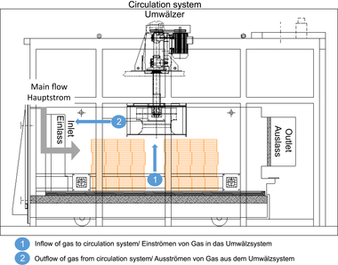
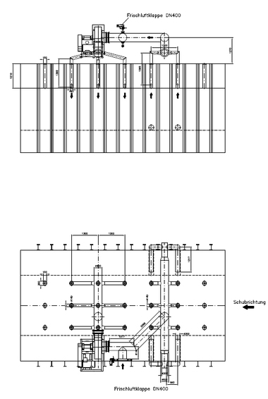
»Figure 2 shows the inside view of the experimental kiln at IZF. The kiln was constructed in 1984 and is 5.9 m in length, 3.8 m in breadth and 4.1 m in height. The usable volume inside the kiln is about 18.5 m³ and the has an internal dimension of 3.9 m as length, 2.8 m in breadth and 1.7 m as height. The kiln is equipped with 6 natural gas burners, each with a power of 180 kW, making the total power of 1080 kW. On the bottom right side, there are two burners and on the right top side there is one burner in the middle. On the left side, the burners are located in a mirrored fashion to the right side. On the two side walls, electrical heating elements have a total power of 230 kW. In the kiln chamber, is an impeller (maximum operating temperature 900 °C). It will extract the air from the middle of the setting (»Figure 3) and will distribute the air in the kiln chamber. This impeller or internal circulation system will enable an increase in the fluid flow through the setting, thereby increasing the convective heat transfer coefficient between the kiln atmosphere and brick. In addition to increasing the convective heat transfer coefficient, it will create a homogeneous kiln atmosphere temperature.
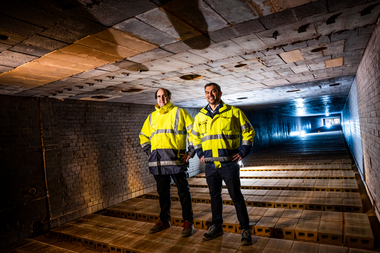
External circulation enables the simulation of longitudinal flow in the tunnel furnace. This air enters the kiln through the inlets provided in the kiln car, as seen in »Figure 4 (left). The air flow through the brick setting, which has a total mass of 3360 kg, will be directed out of the chamber to the external impeller through the honeycomb structure as seen in »Figure 2. This air will be recirculated to the entrance via a rectangular duct at the top of the kiln. In this manner, the experimental shuttle kiln at IZF can recreate a section of the tunnel kiln.
»Figure 3 shows the thermocouple positions in the setting to measure the temperature development in the setting during the experiment. There are total of 24 thermocouples in the setting, 6 in each measuring plane, which are numbered as 1, 2, 3 and 4. At each measuring plane, there are 3 thermocouples at the top and bottom. The 3 different thermocouples measure the temperature at the right, middle and left sections in the top and bottom. In addition to thermocouples measuring the temperature of the setting, the kiln atmosphere temperature is measured.
Experiments were conducted to analyse the influence of atmosphere circulation with heating elements on the sides. The entire duration of the program was 6 hours and the heating rate in the first 2 hours was 150 K/hour, the next hour was 200 K/hour and in the last 3 hours, the heating rate was about 60 K/hour. According to the temperature profile given to the kiln temperature controller, the expected final temperature was about 680 °C after 6 hours.
3 Results and Discussions
»Figure 5 (left) and »Figure 5 (right) show the temperature development inside the setting at two measuring planes (3rd and 2nd), respectively, with the use of electrical heating elements and when the rotational speed of the impeller is at 10 %. The highest temperature in the 3rd measuring plane was at the position which is marked as 3OL (black line), which is on the top left side of the setting and is facing the electrical heating elements on the left side. The thermocouple on the right side of the measuring plane (3OR – dark green line) had malfunctioned during the experiments, and that is the reason for the very high temperatures shown in the graph. The lowest temperature at this plane was at the location in the middle of the setting (3UM – light blue line). It can be seen that, for the first three hours during the experiment, the middle of the setting (3UM) was at a temperature the same as the beginning, whereas the temperature at the side (3OL – black line) was almost 200 °C, which is located at the side of the setting facing the heating elements. The sudden decrease in the temperature after more than 3 hours (3OM – blue line) is because of the sudden switch off of the circulation system. The system was switched on after a few minutes and was in operation throughout the rest of the duration of the experiment which can be seen as the increase in the temperature (3OM – blue line). »Figure 5 (right) shows the temperature development in the 2nd measuring plane. In this measuring plane, the temperature development at the positions 2OL, 2UL, 2OM and 2UM, which represent the left and middle section have the same temperature till 3 hours. The right section of the measuring plane which is represented by positions 2OR and 2UR have almost the same temperature and reaches the same temperature as the left side (2OL and 2UL) after 3 hours. After time 4 hours, the temperature development at the top in the 2nd measuring plane (2OM) starts to lag behind the other positions. Comparing the temperature development in the measuring planes 2nd and 3rd, plane 2 has a more homogeneous temperature development than the measuring plane 3. The operation of the internal impeller at 10% can be considered as the reason for the homogeneous temperature development in this measuring plane. The air in the middle of the section will be extracted because of the rotation of the impeller and will be distributed throughout the atmosphere. The rotation of the impeller causes the air coming from the horizontal direction to be concentrated in the middle of the setting and causes the temperature homogenization in the measuring plane 2.
»Figure 6 (left) and »Figure 6 (right) show the temperature development inside the setting at two measuring planes (3rd and 2nd), respectively, with the use of electrical heating elements and when the rotational speed of the impeller is at 50 %. When the rotational speed of the impeller is increased to 50%, the temperature difference in the 3rd measuring plane is reduced to less than 50 K till the time elapsed reaches 3 hours and increased to about 100 K when 6 hours have passed. The maximum temperature (at time 6 hours) in the 3rd measuring plane is increased to 425 °C (3OL - »Figure 6) from 375 °C (3OL - »Figure 5) and the minimum temperature (at time 6 hours) is increased to 375 °C (3UR - »Figure 6) from 125 °C (3UM - »Figure 5) in comparison to the case when impeller speed is at 10%. In this plane, the temperature development in the middle of the setting is almost similar (3UM - »Figure 6) to the temperature development at the sides whereas when the impeller speed is at 10%, the temperature in the middle (3UM - »Figure 5) did not increase until after 3 hours had passed.
The maximum temperature (at time 6 hours) in the 2nd measuring plane remains almost the same at 450 °C (2UL - »Figure 6) and 450 °C (2OL - »Figure 5) and the minimum temperature (at time 6 hours) is increased to 375 °C (2OL - »Figure 6) from 350 °C (2OM - »Figure 5) in comparison to the case when impeller speed is at 10%. In the 2nd measuring plane when the rotational speed of the impeller is at 50 % (»Figure 6 (right)), the temperature development is highly homogeneous as compared to the case when the rotational speed of the impeller is at 10% (»Figure 5 (right)).
4 Conclusions
The tests conducted at different rotational speeds of the internal impeller demonstrate the effect on the temperature profile within the setting, which is heated by electric heating elements. Atmospheric circulation is an effective means of increasing temperature uniformity within the tunnel kiln and thus achieving the most even heating of the products possible, regardless of the energy source. Convection plays a crucial role in the temperature homogenisation of the setting, which has low thermal conductivity. Of particular significance is the finding regarding the potential overheating of the outer rows of the charge in direct proximity to the electric heating elements on the side walls. The experiment clearly showed that this effect can only be reduced through intensive circulation. However, the question arises as to whether this can be achieved across the entire heated surface area in furnaces with significantly larger cross-sections. Particularly when retrofitting existing facilities, there are structural challenges that require a high level of investment.
Acknowledgement
This study was funded under the Horizon research project eLITHE - Electrification of ceramic industries high temperature heating equipment and the grant agreement number of the project is 101138325.