Numerical simulations, Part 2Thermal conductivity of vertically perforated bricks:
basic principles – measurement – simulation

Numerical methods for determining specific product properties have become established over many years, for example the numerical determination of the transmission of heat through vertically perforated clay bricks. When applied with appropriate software as a tool and adequate knowledge of the physical and mathematical correlations, these methods offer an extremely efficient option for analysing product properties, above all in the scope of product optimization. Absolutely essential for this, however, is also a knowledge of the limitations and the resulting possibilities for the application of numerical methods. This article discusses all relevant aspects concerning the numerical determination of the thermal conductivity of vertically perforated bricks, with the aim of increasing the understanding of and willingness to apply such methods.
In issue 1-2021 of ZI Brick and Tile Industry International, an article by Darya Ivanova M.Sc. from the Brick and Tile Research Institute Essen was published on “Application of numerical simulations for investigation and improvement of the acoustic behaviour of vertically perforated bricks”. This article addresses the construction-related physical property of thermal conductivity as well as the numerical and measurement-based possibilities for its determination.
1 Basic principles concerning thermal conductivity
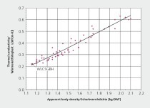
Thermal conductivity is a temperature-dependent, material-specific value of a pure solid body, a pure liquid or a pure gas. It specifies the heat flow in joules that passes through a 1-m² large and 1-m-thick layer of a certain material. The usual symbol for this is the small Greek letter λ (lambda) with the unit J/(m·s·K) or W/(m·K). With regard to thermal conductivity in construction materials, then, strictly speaking, it refers to a mixed form of different heat transfer mechanisms. Especially insulating materials, but also mineral construction materials like a brick body or organic construction materials like wood have a more or less complex pore structure. For such construction materials, besides the thermal conduction via the pure solid body structure, the gas phase as well as liquid water in the pores, thermal radiation between the surfaces of the pores and thermal convection via the air in the pores also occur. For construction materials with medium to high density, e.g. brick body, thermal radiation and convection via the pore structure can be neglected. The key factor in the heat transmission in a brick body are thermal conduction via the solid structure and the pore air.
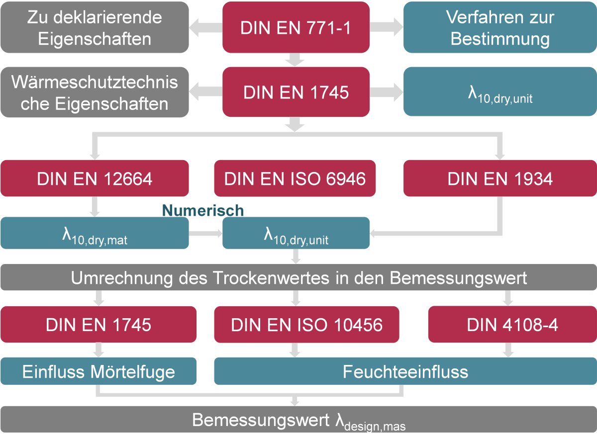
For these reasons, it is common and completely reasonable in the case of these building materials to talk generally about thermal conductivity as a material property. If, however, you look at a vertically perforated brick with its complex web geometry as well as possible insulating material filling of the perforated chambers, generally it is necessary to talk about the resulting thermal conductivity to differentiate it from the pure material thermal conductivity. To differentiate between the different thermal conductivities of the brick body, vertically perforated bricks (VPB) and VPB masonry, DIN EN 1745:2012 [2] provides corresponding characteristics based on indices, the diversity of which may initially appear overloaded, however, these different indices do enable unambiguous communication. Basically, a distinction is made between dry values and the design values for thermal conductivity, which are specified with indices.
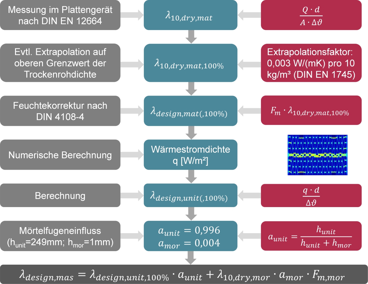
These are the most relevant symbols and indices used in the corresponding standards. »Fig. 2 is intended to show the references and interdependences of the different standards more clearly. The properties of clay masonry units and the methods for their determination are defined in DIN EN 771-1 [3]. For determination of thermal properties such as thermal conductivity, reference is made to DIN EN 1745, which specifies the processes and methods that can be applied for determination of thermal conductivity. Besides the direct measurement of the heat transmission through a test wall specimen with the hot box method in compliance with DIN EN 1934 [4], which returns the λ10,dry,mas value, reference is made to DIN EN ISO 6946 [5] in which the thermal transmission conditions as well as the calculation of the thermal resistance R and the thermal transmittance U are described. Based on determination of the brick body’s thermal conductivity λ10,dry,mat with the hot plate in compliance with DIN EN 12664 [6], the resulting thermal conductivity of the whole vertically perforated brick can be calculated with numerical methods in accordance with DIN EN ISO 10211 [7]. With consideration of the mortar joint influence described in DIN EN 1745 as well as the influence of moisture content according to DIN EN ISO 10456 and DIN 4108-4 [8], the design value can be calculated (»Fig. 2). The design value for the thermal conductivity of a construction material is crucial when it comes to evaluating an exterior component of a building in respect of its energetic quality or its thermal insulating effect and ultimately for calculating the heating requirement for the entire building.
How the design value is determined from the measured value is explained in the following with »Fig. 3. From the applied voltage U and the current strength I, the heat flow Q is calculated, from which based on consideration of the specimen area and thickness and the difference in temperature, the body thermal conductivity λ10,dry,mat can be calculated. Deviations from the upper limit value of the net dry density can be taken into account and corrected accordingly with the extrapolation factor. With the multiplication with the moisture content correction factor Fm according to DIN 4108-4 for bricks, the influences of the equilibrium moisture content at 80 % rel. humidity and 23 °C on the thermal conductivity is taken into consideration. With the design values for the thermal conductivity for the brick body and a possible filling of insulating material, the heat flow density corresponding to the geometric vertically perforated clay block model in 2D is calculated with FEM software. Based on the heat flow density, the thickness of the brick and the temperature difference between the surfaces of the warm and cold sides, the design value of the clay brick λdesign,unit(,100 %) is calculated. Since it is a 2D model, the influence of the mortar joint is taken into consideration in a simplified way proportional to the surface area. Starting from a mortar joint thickness of 1 mm and a brick height of 249 mm, area percentages from 0.4 or 99.6 % result. The design value for brick masonry is calculated in accordance with Fig. 3 with consideration of the moisture content correction factor of mortar corresponding to DIN 4108-4.
2 Measurement of the body thermal conductivity
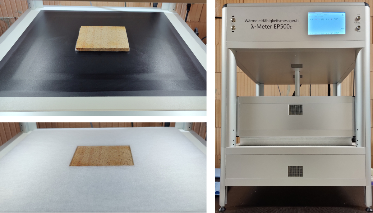
The key input value for numerical determination of the heat flow Q through a vertically perforated brick and the resulting thermal conductivity λ10,dry,unit or λ10,dry,mas derived from this is the measured body thermal conductivity λ10,dry,mat and, if appropriate, the thermal conductivity of an insulation material filling. As both the measurement and the subsequent simulation are performed under stationary boundary conditions, consideration of the body density and specific thermal capacity is not necessary, however, the measured body density can be useful in the evaluation of the results. The measurement of the body thermal conductivity at the Brick and Tile Research Institute Essen is performed with a new single-plate device in compliance with DIN EN 12664:2001 as well as with the ISOMET rapid test for verification. Any necessary measurements of the thermal conductivity of an insulation material filling are performed in the same device, however, in compliance with DIN EN 12667. The single-plate device is a measuring device with which the heat flow through a test specimen is measured. For the measurement of the heat flow through the test specimen, the horizontal heat flows on the level of the test specimen and the heating plate must be minimized. For this purpose, the test specimen is embedded in a specimen holder made of thermal insulating fleece (»Fig. 4).
Beforehand, the specimen is cut out of an outer web element of the corresponding vertically perforated brick, ground on parallel planes, and cut to the dimensions of the measuring area. The prepared test specimen is then dried at 105 °C to constant weight and then cooled in the desiccator to prevent absorption of moisture from the ambient air. The test specimen is then inserted in the single plate device. Between the heating and cooling plate a defined temperature gradient is set, from which the heat flow through the test specimen results. The heat flow is calculated from the power that must be fed to the heating plate. The measurement is conducted under stationary boundary conditions. From the constant heat flow Q (heating power) in stationary state, the thickness d and the area A of the test specimen as well as the temperature difference, the thermal conductivity of the absolutely dry material specimen is calculated according to Equation 1 at an interval of 30 seconds (»Fig. 3).
3 Numerical determination of the resulting
thermal conductivity
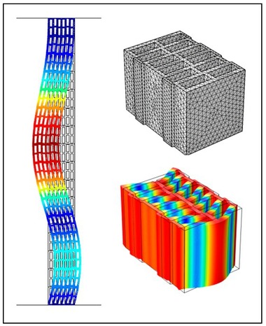
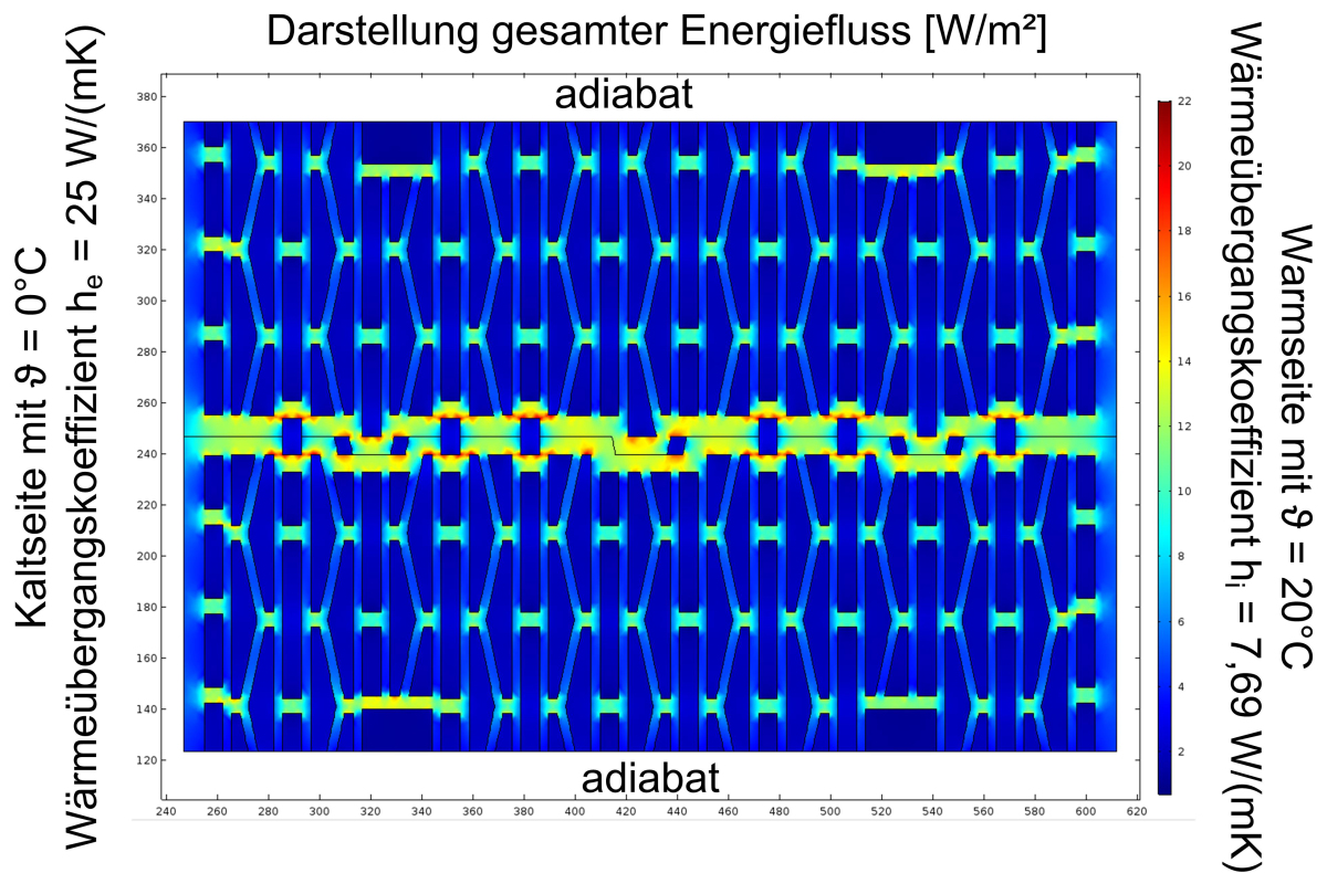
For the numerical determination of the resulting thermal conductivity, DIN EN 1745 prescribes that the FEM software must fulfil the boundary conditions and specifications in DIN EN 10211. This is the standard for describing thermal bridges in buildings by means of detailed calculations. All common thermal bridge programs validated in compliance with DIN EN ISO 10211 are therefore also suitable for calculation of the resulting thermal conductivity of vertically perforated bricks as here nothing other than heat flows and surface temperatures are calculated. Common to all these programs, however, is the simplified approach for consideration of heat transmission by radiation and convection is accordance with DIN EN ISO 6946, in which equivalent thermal conductivities are used for air-filled chambers. As in the scope of research, it is often necessary to look at the heat transmission mechanisms separately, a model in the Comsol Multiphysics FEA software was applied and there heat conduction was coupled with heat radiation. The model was then adapted to fulfil the requirements of DIN EN 1745 and DIN EN ISO 10211 and validated. Heat transmission by means of convection within the air-filled perforated chambers can be neglected in most cases as large chambers are filled with insulation material and filigree perforation patterns have such small chambers in which convection is negligible [9] [10] [11]. For description of the numerical model, »Fig. 4 shows the result of a calculation of the energy flow.
According to the specification of DIN EN 1745, the vertically perforated brick is separated in the axis of symmetry in the thickness direction and joined together again in the area of the vertical joint. In this way, allowance is made for an increased energy flow in the area of the vertical joint. The thermal transmittance coefficients for inside and outside are specified in DIN EN ISO 6946. In this case, they describe in the transmittance of an amount of heat at the boundary surface from the room air to the wall surface and from the outside surface to the exterior air. For the purpose of simplification, in building construction constants are assumed, which can be calculated from the convective heat transmission, which is largely determined by the flow velocity of the air flowing past, and the heat transmission as a result of radiation, which can be largely calculated from the thermal emissivity in connection with the Stefan-Boltzmann law. From the calculations, on the basis of the temperature boundary conditions, a wind velocity of 4 m/s outside as well as a typical emissivity for mineral building materials of 0.9, the heat transmittance coefficients shown in »Fig. 4 result. Instead of the temperature boundary conditions with 20 °C inside and 0 °C outside, in the numerical calculation, naturally, also 1 °C inside and 0 °C outside would lead to the same results, as a linear relationship exists between the heat flow density and temperature difference, and the thermal conductivity is always relative to a 1 K temperature difference. The temperature difference of 20 K has been taken from the measurements to better compare the determined surface temperatures and heat flows. The outer boundary conditions of the model are thus now described.
For the calculations, however, the material parameters and the radiation boundary conditions must still be assigned. The measured body thermal conductivity is assigned to the entire web surface area. If it is not yet possible to determine this, as the investigation concerns a possible web geometric optimization and the material is not yet final, then by means of simulation with two different body thermal conductivities, the linear relationship to the resulting thermal conductivity of the entire vertically perforated brick can be shown graphically or calculated based on the corresponding linear equation. In this way, it is possible to estimate approximately what body thermal conductivity is needed with the correspondingly studied geometry to achieve a desired resulting thermal conductivity of the masonry. Useful, here, is especially the relative comparison between a known geometry and variations as part of product optimization.
If the perforation chambers are filled with insulating material, this must also be assigned a corresponding material thermal conductivity. Then it is merely a case of heat transport in solids, which is limited to thermal conduction. If the chambers are not filled, a fluid structure coupling is present, in which for the fluid (air) in addition to the temperature-dependent thermal conductivity the radiation boundary conditions must also be defined. For this purpose, the emissivity ε and the radiation physical boundary conditions, which should apply for the surfaces, are assigned to all inner surfaces that mutually transfer radiation heat. This is effected with so-called diffuse-spectral surfaces for which the radiation balance for every node on a surface is calculated on the basis of the Stefan-Boltzmann law, corresponding to the surface temperature and the emissivity. Accordingly, all input parameters required for the numerically assisted calculation of the resulting thermal conductivity of vertically perforated bricks are described and defined.
4 Typical applications
A small comparison in »Table 2 shows the results of wall measurements in the test setup in compliance with DIN EN 1934 as well as numerical simulations and subsequent calculation of the design value for masonry.
The difference between measurement and numerical calculation ranges between -1.5 and -6 % relative to the measurement result. The differences arise because of many factors. The biggest difference consists in respect of the constant, ideal boundary conditions and material parameters, without natural variation. Here, on the one hand, simulation offers an advantage, as the results are completely and permanently reproducible and so the relative comparison of different variations can be related directly to the parameters or geometry variations. This is hardly possible for measurements as no constant boundary conditions exist. On the other hand, it is precisely the ideal boundary conditions and simplifications like the two-dimensional consideration and isotropic materials properties that lead to completely plausible differences, which must be taken into consideration in the evaluation. Nevertheless, the calculation under these boundary conditions is sufficient for an estimation of the expected measured result with sufficient accuracy, especially when reference values are available.
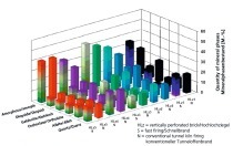
In »Table 3 below, on the basis of slightly abstracted geometries, the possibilities of the relative comparisons are shown at least to some extent. There are no limits to geometric variations, irrespective of curves, arches, diagonals, holes, everything can be taken into account with numerical methods and evaluated with regard to the impact on the resulting thermal conductivity. So it is possible to say whether a variation on the product would tend to effect an improvement or deterioration. Especially the parallel comparison of the impact on sound transmission and thermal conductivity are particularly important here. Show here are abstracted geometries that are intended to merely show the possibilities and basic principle of how relative comparisons can be made.
Part of the results is certainly at least known qualitatively, like, for example, the improvement of the resulting thermal conductivity with staggered web elements in the direction of the wall thickness. The results become more interesting when the differences between one central web elements and two thinner central web elements with the same combined thickness are considered in respect of thermal conductivity and sound transmission. The difference in thermal conductivity is very small at 0.7 %, in the consideration of the frequency-dependent sound reduction index it will, however, become evident that a considerable improvement results, especially in the high frequencies from 1 000 Hz, as the drop in the range of the thickness-mode oscillations is much lower on account of the greater stiffness of the geometry and is shifted to higher frequencies. That is not as yet a universally valid statement and individual cases should be investigated in detail, however, such web-geometry- and material-specific correlations are being systematically investigated in an ongoing research project.
5 Possibilities and limitations
It generally applies that the results yielded by a measurement or a calculation, irrespective of whether this is analytically or numerically resolved, must be critically scrutinized and checked for plausibility. There are sources of error for both options. Measurements in test setups are always subject to the influence of external boundary conditions, which can be minimized but not completely excluded. The human factor can be a source of error both in measurements and calculations, which, however, can also be minimized with appropriate qualification. Measurements in test setups, irrespective of whether the sound reduction index or heat transmission is to be determined, are necessary and also specified as such in national technical approvals in Germany. The numerical determination of sound transmission and heat transmission through vertically perforated bricks should, however, be the preferred option in the early phases of product development, that is before a die is produced for the brick.
With the numerical methods, an exceptionally efficient possibility is now available for evaluation of the expected sound reduction and thermal conductivity. In this early phase of a product development or optimization, simulation offers the only possibility to carry out a relative comparison of the product property being tested that is limited exclusively to the geometry or material parameters of the product, as the boundary conditions are ideal and constant. In addition, big savings result in the costs for material, time, production and energy costs. The models function so well that as part of a relative comparison reliable statements can be made. Moreover in the scope of an integrated study of the product being tested, it is possible to estimate the expected product properties with an acceptable level of accuracy. For such an estimation, however, it is necessary to be aware of the limitations of the applied numerical methods.
If numerical determination of heat transmission through vertically perforated bricks on the basis of an existing perforation geometry and the measured body thermal conductivity is commissioned, then from the outset it must be clear that the numerical result cannot correspond exactly with the expected result of a wall measurement in a heat box. There are manifold reasons for this, significant, however, are the ideal boundary conditions, the constant material parameters and the simplification with the consideration of a two-dimensional geometry in the numerical model. For these reasons, the numerically determined thermal conductivity values are around 1.5 to 6 % lower that the values obtained from measurement of a wall. It is essential that this is taken into account and communicated in the evaluation of the absolute results. For relative comparisons, numerical methods are very suitable and much better than measurements as the influence of the boundary conditions and material deviations is factored out and the comparison is related directly to the material parameters or changes in geometry. Only when a variation is found to be suitable according to the numerical studies, should small quantities then be produced and tested in measurements.
6 Summary
Numerical methods can and should replace complicated and expensive measurements in the early stages of product development or product optimization when it comes to evaluating a development based on relative comparisons of the relevant properties like, for example, thermal conductivity. In many cases these methods are more suitable as results are reproducible and external influences are excluded and because a direct evaluation as well as isolated consideration of the different options for optimization is possible. Such methods are also suitable for estimation of the expected measured values, here the results must, however, be evaluated in respect of the limitations of the numerical model and communicated appropriately. Applied in this way, the numerical methods present an efficient and sustainable possibility for the study of product properties as resources can be preserved.