“Natural Gas and Hydrogen – What’s New?” Findings from Laboratory and Field Studies (part 2 of 3)


4.3 Properties of the fired HMz (backing brick)
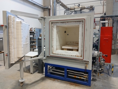
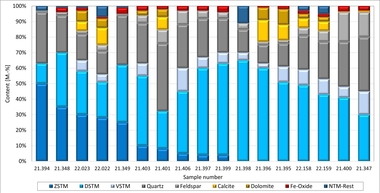
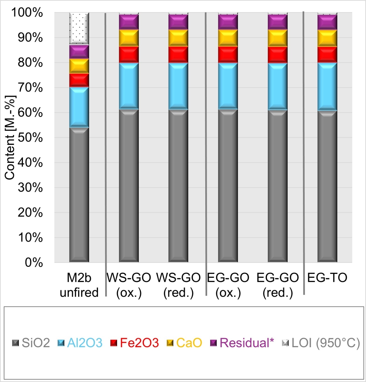
After being fired with natural gas in the tunnel kiln as well as with hydrogen and natural gas in the chamber kiln, the bricks exhibited a uniform brick red surface. The bricks from the tunnel kiln were coloured homogeneously red throughout, while the bricks fired in the chamber kiln exhibited grey cores. To determine the composition of the oxidized and reduced areas, samples were taken. The designation (ox.) refers to the areas with red colouring, the designation (red.) to grey-coloured areas. »9 left shows the mineral content, »9 right the chemical composition of the unfired Mix M2b as well as of the fired red and grey material after firing with hydrogen and natural gas in the chamber kiln and with natural gas in the tunnel kiln.
The mineral content of the unfired and fired Mix M2b shows that during firing in both kilns, kaolinite, smectite, calcite, pyrite as well as the organic components decomposed completely and the content of amorphous silicates increased. The clay minerals muscovite, illite and chlorite only decomposed incompletely. In addition, haematite, feldspar (anorthite and oligoclase) and gehlenite were formed.
Firing in the chamber kiln with hydrogen and natural gas led to a higher content of amorphous silicates and feldspar along with less muscovite, illite and gehlenite than in the tunnel kiln. After the firing with hydrogen, the content of amorphous silicates and of haematite was somewhat lower than after the firing with natural gas.
The oxidized and reduced specimens from the chamber kiln differ slightly. In the red-coloured material, somewhat more haematite and somewhat less quartz were determined than in the grey-coloured material. Here, there is only an insignificant difference between the outcomes with hydrogen and natural gas. The chemical composition of the unfired and fired Mix M2b evidences that – as expected – there are no differences in chemical terms between the differently coloured areas. The oxide content increases in the fired material by 12 to 13 % and corresponds to the loss on ignition of the raw material. In the reduced material, traces of residual carbon were determined by means of C/S analysis (up to 0.24 mass% TOC).
The results of the magnetic susceptibility of Mix M2a before and after firing in the gas and tunnel kiln are shown in »10. The oxidized and reduced specimens were analysed individually.
The colour of the bars corresponds approximately to the colour of the material. The reduced grey material has lower magnetic susceptibility than the oxidized red material. The lower magnetic susceptibility of the reduced material evidences that apparently no magnetite was formed from the primary iron minerals goethite, haematite and pyrite. The finding indicates rather the existing residual carbon that can also colour the material grey.
In addition, the scanning electron microscope was used to capture images of the grey and red material fired with hydrogen and natural gas. Here, no differences in the pore structure were observed between the different kiln atmospheres and the type of kiln as well as between the oxidized and reduced areas.
The compressive strengths and bulk densities of the bricks from Mix M2b after firing in the gas and tunnel kiln with hydrogen and natural gas are shown in »11. In each case, these were averaged from three individual values, while the mass loss and firing shrinkage were calculated from four individual values.
While the bulk densities and mass losses neither differ nor scatter, the compressive strengths and firing shrinkages do differ and are widely scattered. In the case of firing with hydrogen in the chamber kiln, a higher strength as well as firing shrinkage were reached than in the firings with natural gas in the gas-heated chamber kiln and in the tunnel kiln.
4.4 Gas-heated chamber kiln
4.4.1. Fuel gas and combustion air volumes
The starting data for calculation of the energy, combustion air and exhaust gas volumes as well as the CO2 emissions for the fuel gases used, i.e. hydrogen and natural gas, are shown in »Table 3.
In »12, the measured fuel gas volumes are shown: left summarily during the firing time and right as the volume flow dependent on the measured kiln temperature.
»12 left shows that – independent of the type of fuel gas – the firings with the already fired material have a higher fuel gas consumption than with the unfired material. The difference can be attributed to the organic constituents present in the unfired material as these support the heating as a result of their burn-out from a kiln temperature of around 400 °C. From the specified gas consumptions, it is clear that the volume of the hydrogen used for the fired material amounts to 3.26 times and for the unfired material 3.19 times the volume of the natural gas.
In »12 right, both the gradients of the kiln temperature (red) and the volume flows of hydrogen (blue) and natural gas (brown) are shown as a function of the kiln temperature. With increasing temperature or with temperature gradients greater than zero, the consumption of both fuel gases increases. The volume flow of the fuel gas also follows the temperature gradient. If this increases, the fuel gas volume increases and vice versa. This (differentiated) presentations also shows the following energy-consuming and -releasing reactions of the unfired material for both fuel gases as a function of the kiln temperature:
Between 250 and 400 °C, a slight increase in the consumption of the fuel gas is observed. In this temperature range, endothermic expulsion of the physically bound water occurs.
Between 400 and 670 °C, the gas consumption decreases in comparison with the fired material. In this range, the exothermic burnout of the organic components takes place. With natural gas, burnout only starts from around 430 °C.
Between 670 and 820 °C, the gas consumption for the unfired material is greater than for the fired material. Here, in endothermic reactions the clay minerals dehydrate and the carbonates deacidify.
Between 820 and 890 °C, the gas consumption is decreased in comparison with the fired material. Here, burnout of any residual organics can be expected.
The numbers in the right figure specify the temperatures at which the curves intersect. The reduced gas consumptions on account of the material reactions were observed in the case of both fuel gases in approximately the same temperature ranges. Here, it should be noted that the temperatures measured in the material were lower than the kiln temperatures. The reactions of unfired material depending on the material temperature are shown and discussed in 4.4.3 and »16.
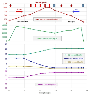
In »13, the measured volumes of combustion air are shown: left summarily again during the firing time and right as a volume flow as a function of the measured kiln temperature. As experience has shown, the volume of combustion air increases with increasing temperature and rising gas consumption in the kiln. After the end of the heating, the combustion air was used for cooling and is not shown in the interest of clarity.
In »13 left, it is clear that the firings with the already-fired material have a higher air consumption on account of the higher fuel gas requirement than for the unfired material. In addition, it was determined that the combustion air volume in the case of hydrogen was only 0.84 times the combustion air volume of the natural gas for the fired material and 0.83 times its volume in the case of the unfired material.
»13 right shows both the gradients of the kiln temperature (red) and the volume flows of the combustion air for hydrogen (blue) and natural gas (brown) as a function of the kiln temperature. With increasing temperature or with temperature gradients greater than zero, the volume of air required increases together with the fuel gas consumption. The volume flow of the combustion air also follows the temperature gradient. If this rises, the volume of air increases and vice versa. This differentiated presentation shows the same energy-consuming and -releasing reactions of the unfired material as can be seen in the temperature gradients in »15.
To summarize, it can be determined that the measured values confirm the additional consumption of fuel gas volume and the lower combustion air volume of hydrogen calculated in [5] compared to those for natural gas and methane.
4.4.2 Energy consumption and exhaust gas volume
From the measured fuel gas volumes, and with the calorific values in »Table 3, the respective energy consumption was calculated in accordance with Equation 1.
HOfen = Hi,n * VBG,n (1)
HOfen Energy consumption of the kiln [kWh]
Hi,n Calorific value of the fuel gas, relative to the standard volume [kWh/Nm³]
VBG,n Volume of the fuel gas, measured, relative to the standard volume [Nm³]
The exhaust gas volume of the kiln was not determined, as a thermal afterburning system with a natural gas burner and draught diverter is directly connected to the firing chamber. As the combustion air ratio was the same in all firings (cf. »2), the exhaust gas volume was calculated from the measured fuel gas and combustion air volumes less the theoretical combustion air volume for λ = 1 (values from »Table 3) in accordance with Equation 2.
VAG,ber,n = VBG,mess,n * RVL/BG + VVL,mess,n – VVL,ber,n (2)
VAG,ber,n Volume of wet exhaust gas, calculated, relative to the standard volume [Nm³]
VBG,mess,n Volume of fuel gas, measured, relative to the standard volume [Nm³]
RVL/BG Volume of combustion air for each fuel gas for λ = 1 [Nm³/Nm³] (cf. »Table 3)
VVL,mess,n Volume of combustion air, measured with λ > 1, relative to the standard volume [Nm³]
VVL,ber,n Volume of combustion air, calculated for λ = 1, relative to the standard volume [Nm³]
The calculated energy consumptions and exhaust gas volumes are shown in »14. After heating, the exhaust gas consists of cooling and leakage air as well as the residual decomposition products from the raw material and is not shown here for the purpose of better clarity.
In »Table 4, the measured results from »12 to »14 are compared with the values calculated in [5] and [6].
The theoretically expected volumes of fuel gas, combustion air, exhaust gas and water vapour (right column) were calculated for hydrogen and methane for a stoichiometric combustion with λ = 1 [5], the energy saving of 3 % in [6] on the other hand for a tunnel kiln with real air ratios and the software SimKilnT.
The measured fuel gas volumes for hydrogen were 3.26 and 3.19 times the natural gas volume (values for fired and unfired material respectively). In addition, for hydrogen, the combustion air volume was reduced by 16 and 17 % respectively, the wet exhaust gas volume by 9 and 10 % respectively and associated with this the energy consumption by 7 and 9 % respectively. These values are in near agreement with the calculated values from [5] and [6].
The ratios determined from the measured values are somewhat greater for the fired material than for the unfired material. One reason for this can be the thermally reactive raw material. In addition, the mass of the fired ware was only 81 % of that of the unfired material. The lower mass resulted not only from the mass loss during firing but from the grinding of the bricks for determination of their compressive strength.
The difference from the energy consumption of the firings of fired and unfired material is 13.9 kWh for hydrogen and 11.0 kWh for natural gas. This difference can be attributed to the release of the energy from the unfired raw material. The total energy that a material needs during firing is calculated from the energy for heating the material and the raw material enthalpy as follows:
dHM = dHH + dHR (3)
dHM Enthalpy of the material in total [kWh]
dHH Enthalpy for heating the material from the ambient to the maximum temperature [kWh]
dHR Raw material enthalpy of the unfired material [kWh]
The energy for heating the material is calculated from:
dHH = cp * m * dT (4)
cp Specific heat capacity of the material: unfired = 0.80 kJ/kgK, fired = 0.90 kJ/kgK, [7]
m Mass of the ware fired; unfired = 51.8 kg, fired = 42.0 kg
dT Temperature difference from Tmax - TUmgeb. with (896 °C – 15 °C) = 881 K
The raw material enthalpy results from the content of adsorption moisture, organic carbon, pyrite, water from the clay minerals and carbonates as in »Table 5 (cf. [8]).
The adsorption moisture corresponds to the mass loss of the material in thermogravimetry up to 200 °C (cf. »17). The TOC and TIC contents were determined by means of carbon analysis, the pyrite content by means of XRD. The water percentage from the clay minerals corresponds to the mass loss between 410 and 610 °C or 10 % of the clay mineral content. The calcite content was calculated from the TIC content and determined by means of XRD. The mass loss from the organic carbon is calculated from double the mass of wood with the assumption that the wood burns without residue. The negative mass loss of the pyrite results from the release of sulphur with a mass loss and the mass increase as a result of the oxidation of the iron to Fe2O3. This was detected in the fired material in the form of haematite (cf. »9 left).
The raw material enthalpy is negative overall (exothermic) as the exothermic reactions of the organic carbon and the pyrite superpose the endothermic reactions of water and calcite. In total, the unfired material therefore delivers 9.6 kWh energy and consequently reduces the fuel consumption in comparison to fired material. If, in addition, the different masses of the fired and unfired materials are taken into consideration, the following picture results (cf. »Table 6).
According to Equation (4), the fired material needs 9.2 kWh for heating whereas the unfired material needs 10.0 kWh on account of its greater mass. The negative raw material enthalpy of -9.6 kWh reduces the latter to 0.4 kWh, which the unfired material additionally needs in total for firing. The difference from the energy consumption of fired and unfired material results in 8.7 kWh. This value is in the same order of magnitude as the measured consumptions. Nevertheless, it is somewhat lower than that determined for hydrogen with 13.9 kWh and for natural gas with 11.0 kWh. One cause can be found in the influence of the ambient temperature and the air pressure during the firings.
The expected mass loss caused by the decomposition reactions in accordance with »Table 5 is 14.7 mass%. With the thermal analysis, a mass loss of 13.9 mass% and at the chamber kiln of 14.0 mass% were determined. The differences can be explained with the small quantities of materials in the XRD and STA measurements compared to the mass of four large-size HMz bricks as well as the different residual moisture contents.
Summarizing, it has been determined that the measured values confirm the lower gas and therefore energy consumption as well as the lower combustion air and exhaust gas volumes for hydrogen calculated in [5] and [6] in comparison to natural gas and methane. The differences between the measured and calculated values are attributed amongst other things to the fact that the actual properties of the fuel gases used can deviate from those in »Table 3.
4.4.3 Temperature curve and material reactions
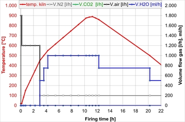
The temperatures measured in the kiln and in the material during the four firings are shown in »15 left as a function of the firing time. The figure on the right shows the gradients (dT/dt) calculated from the temperatures and time in each case as a function of the kiln temperature.
»15 left shows that the material temperatures follow the kiln temperature in time although the temperatures in the already-fired material rise faster than in the unfired material. In the fired material, first a delay in the rise in temperature occurs. This time lag of around two hours decreases with increasing temperature in the kiln to one hour at 750 °C kiln temperature and can be explained with the increase of convection and thermal radiation in the heat transfer.
The delays for the unfired material are caused by the higher setting mass, the discontinuities in the course of the firing on the other hand by the endo- and exothermic material reactions. At 100 °C material temperature, first the residual moisture in the material dries. Between 150 and 500 °C, the material temperatures approach the kiln temperature again. This is when the organic components burn out. Between 450 and 650 °C material temperature, another temperature sink appears, which can be explained with the dehydration of the clay minerals. From 800 °C kiln temperature, the heating rate decreases. The unfired material on the other hand does not change its linear temperature rise and approaches the kiln temperature. This clearly indicates that the material is additionally heated by its inner energy.
»15 right shows the temperature gradients in the kiln and material calculated from the temperatures and firing time as a function of the kiln temperature. From this, it can be seen again that the gradients in the fired material follow the gradient of the kiln temperature. From 450 °C kiln temperature, the material gradients exceed those of the kiln – here, greater heat transfer by convection and radiation is expected.
The gradients in the unfired material show, on the other hand, clear deviations from the kiln gradient. The temperatures of the unfired material in the case of hydrogen-fuelled firing rush ahead of the temperatures measured with the use of natural gas both during heating and during cooling. This phenomenon can be attributed to a different position of the thermocouples in the material during the two firings. Consequently, it is possible that the thermocouple during the hydrogen firing had less contact to the material and was influenced more strongly by the kiln temperature.
For presentation of the material reactions, in »16 the same temperature gradients were plotted against the temperature of the respective thermocouple, i.e. the kiln gradients against the kiln temperature, the material gradients against the material temperatures.
In »16 left, the temperature gradients in the kiln (red) and in the fired material are shown for the two fuel gases (blue – hydrogen, brown – natural gas).
Below 200 °C, the material gradients are smaller than the kiln gradients as heat transfer into the material takes time.
During heating, the material gradients up to around 450 °C are somewhat larger for hydrogen than for natural gas. Here the material heats faster than during the natural gas firing. This phenomenon can be attributed to the different position of the thermocouples in the material. In addition, in this temperature range, the thermal afterburning system influences the kiln temperature. During the hydrogen firing the thermal afterburning system was switched on only above 250 °C so that the CO2 formed in the thermal afterburning systems did not distort the CO2 signal of the exhaust gas measurement.
From 450 °C, the gradients of the hydrogen and natural gas firing only differ insignificantly.
From 650 °C, the material gradients follow the kiln gradient. From 600 °C up to cooling, the gradients in the hydrogen and natural gas firings are close to each other and are larger than the kiln gradient. This can be attributed to the greater heat transfer by convection (burner exhaust gas) and radiation, which increase with rising temperature.
Cooling between 900 and 750 °C proceeds comparatively quickly, the material therefore follows the kiln gradients much more slowly.
In »16 right the temperature gradients in the kiln and in the unfired material are shown.
The unfired material shows during heating between 70 and 110 °C a sink caused by the residual material drying. During this process, energy is consumed, the material temperature falls and the gradient is decreased.
Between 150 and 350 °C, the gradients exceed those of the fired material and the kiln. This is caused by the heat-releasing reaction during burnout of the organic components.
Between 450 and 550 °C, the gradients of the unfired material are much smaller than in the fired material and in the kiln. In this interval, dehydration of the clay minerals takes place, preventing faster heating of the material.
Between 550 and 670 °C, the unfired material heats faster than the fired material and the kiln. In this interval, the exothermic oxidation of the residual carbon takes place.
From 670 °C, a discontinuity can be observed in the case of the unfired material, which does not occur with the fired material. Because of the residual carbon, the unfired material shows somewhat larger gradients than the fired material. The discontinuity at 760 °C indicates the endothermic deacidification of the carbonates.
»15 During cooling the gradients of the unfired material follow those of the fired material and the kiln. At around 810 °C the material gradient rises sharply both in the case of the hydrogen and the natural gas. As a result of the infeed of oxygen-rich cooling air, here more residual carbon from the material burns off. This assumption is confirmed by the sudden increase in the CO2 content in the exhaust gas at 810 °C (cf. 4.4.4).
»17 shows the material reactions of the thermal analysis for comparison with the material reactions in the chamber kiln.
The DSC curve first shows an endothermic reaction between 50 and 140 °C associated with a mass loss in the TG curve, which describes the residual drying. From 200 °C, two reactions overlap with respective mass losses. The first reaction is strongly exothermic and takes place as a result of the oxidation of the volatile organic components. At 500 °C, an endothermic reaction with a further mass loss is superposed, which is caused by the dehydration of the clay minerals. Between 650 and 730 °C, another endothermic reaction with mass loss takes place, which is caused by deacidification of the carbonates.
The reactions from the thermal analysis are reflected in the gradients of the unfired material in the chamber kiln. Irrespective of the type of fuel gas, however, dehydration of the clay minerals takes place at 20 K higher and carbonate deacidification at 40 K higher temperatures than in the thermal analysis. In this comparison, it should be taken into consideration that the heating rate of the thermal analysis at a constant 600 K/h is much higher than in the chamber kiln and here the heating rate also varied during the firing time. In the thermal analysis, the material mass with 40 mg is much lower than that in the chamber kiln. Experience has shown that all this shifts the material reactions to high or lower temperatures. In addition, a large compact material mass leads to incomplete oxidation of the organic components and unburned residual carbon.
In the chamber kiln, the material gradients of the carbonate deacidification differ slightly for hydrogen (peak at 758 °C) and for natural gas (peak at 768 °C). The material-related CO2 content in the kiln at this temperature is around 13.7 vol% and thus around 3.3 times higher than for hydrogen with around 4.1 vol% (cf. »21 and »19). From this it is apparent that the different levels of CO2 content in the hydrogen and natural gas firings have an insignificant influence on the temperature of the carbonate deacidification.
The volatile organic components in the unfired material in the chamber kiln lead to a disproportionate rise of the material gradients already from a material temperature of 200 °C. In this context, it should be noted that in the kiln at the same point in time the temperature had already reached around 400 °C and the temperature in a perforated HMz is always a mixed temperature between kiln and material. On account of the large material mass in the chamber kiln, complete burnout of the organic carbon only took place at higher temperatures. That is shown by the increased material gradients at 608 °C during heating as well as during cooling at 810 °C as a result of the infeed of cooling air.
Summarizing, it has been established that the chamber kiln firings performed can be compared with the measured kiln and material temperatures. It has been shown that the temperatures of the fired material follow the kiln temperatures and the two fuel gases have no significant influence on the firing process and the ware fired. In the unfired material, in addition to the heating rate of the kiln, reactions occurred, which at their characteristic temperatures reduced or accelerated heating of the material. These endo- and exothermic reactions were in similar temperature ranges as in the thermal analysis. The material reactions were independent of the type of fuel gas used.