Using Hydrogen to Decarbonize the Brick and Tile Industry
![»Figure 1: Illustration of a tunnel kiln process with temperature profile (adapted from Specht [2])](https://www.zi-online.info/imgs/2/2/2/4/2/3/9/Figure_1-018d632e718f916a.jpeg)
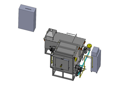
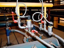
![»Figure 2: Mixing unit of the burner from Kueppers Solutions [3]](https://www.zi-online.info/imgs/2/2/2/4/2/3/9/Figure_2-4315f243f955f599.jpeg)


Abstract: For a significant reduction of carbon dioxide (CO2) emissions, it is assumed that hydrogen (H2) will substitute natural gas in the upcoming years. Therefore, the operational limitations of the existing burner technology must be examined when the hydrogen content in the fuel is increased. To investigate the H2-readiness of typical burners, numerical simulations and experimental investigations were carried out in test facilities and in an industrial tunnel kiln system in the brick and tile industry. The results of the examination of the existing conventional burner for natural gas and an additive manufactured dual-fuel burner for natural gas and H2 will be presented. The investigations carried out so far suggest that it is possible to use H2 in addition to natural gas as a fuel gas for tunnel kilns in the brick and tile industry.
1. Introduction
The main energy sources used for the production process of bricks are natural gas for the firing and drying process and electricity for the rest of the processes like mixing of raw materials, extrusion and shaping. During the production of bricks, clay is pressed into the desired shape, dried, and then often fired in a tunnel kiln. Numerous optimizations of the tunnel kiln process have been carried out in the past decades, which have led to a significant increase in energy efficiency. The report which describes the roadmap for the climate neutral production in the brick and tile industry by 2050 [1] emphasizes that further technological developments have to be made to achieve a reduction in CO2 emissions. The reduction or avoidance of CO2 emissions can mainly be achieved by substitution of fossil fuels with energy from renewable sources. In this context, the focus is on the use of “green” H2.
As the amount of H2 available will be limited in the coming years, it is important to have flexible solutions which can switch between natural gas and H2. To ensure the required flexibility, a new burner concept with a separate gas supply for natural gas and H2 was developed by Kueppers Solutions GmbH. This concept allows the use of the pure gases as well as their mixing directly inside the burner. The dual fuel mixing unit developed for this purpose ensures optimum mixing and flow control of the fuel gas with the combustion air. This in turn leads to efficient combustion and low pollutant concentrations in the exhaust gas. Natural gas and H2 differ in their material properties and combustion behaviour. Especially the differences in density and air demand (volume flows, flow velocity) as well as ignition energy and flame velocity (stability, position and shape of flame) are challenging for the design of a dual fuel burner.
The mixing unit has been designed to consider the properties of natural gas and H2 and to create a flame which is independent of the fuel gas. At the end, understanding how the different gases or blends of natural gas and H2 affect product quality and the emission of pollutants are of great importance for companies of the brick and tile industry.
1.2 Aim of this Paper
In this paper the results of tests on a conventional natural gas burner and on the recently developed dual fuel burner will be shown shortly. Experimental results and simulations for operation with natural gas and H2 are discussed and compared. Complementary simulations of the tunnel kiln are performed to understand the flow topologies in the kiln and the influence of the burner. This can also provide an insight into the temperature distribution in the kiln. Tests with natural gas and H2 were carried out in laboratory kilns with downscaled burners in order to prove the function of the new burner and to be able to evaluate the effects of the combustion gas on product features. Burner tests on an industrial scale were carried out at test rigg to examine flame stability, flame shape and NOx emissions. Finally, tests were carried out on in an industrial kiln which was equipped with the new burners.
2. Brick and Tile Production
»Figure 1 shows an illustration of a typical tunnel kiln process. Kiln cars with green bricks (clay products/bricks before being fired) enter the kiln from the left side and pass through the preheating, firing and cooling zones, each with a predefined heating and cooling rates. Gas and bricks move through the kiln in opposite direction. Cold air enters the kiln where the kiln cars exit, and heat is transferred from the warm bricks to the air. After passing through the firing zone, the hot flue gases flow through the preheating zone and thereby transferring heat to the green bricks.
During firing in the tunnel kiln, numerous chemical reactions and physical processes take place. The arrangement and operation of the burners is designed to achieve uniform temperature distribution and heating of the stacked bricks. Typically, high-speed burners and lance burners with a high outlet momentum are used in this type of kiln. These burners create a turbulent circulating flow between and inside the stacks of bricks which leads, together with the primary flow, to a good heat transfer.
3. Burner Design and Investigation for Dual Fuel Operation
In order to use two different gases in one burner, geometric adjustments to existing burners or a completely new design had to be developed. Due to different gas properties, the way in which the fuel gases are mixed with the air flow is different for H2 than for natural gas. In particular, the differences in density, the required volume flows and flow velocities as well as the flame stability are a challenge for the design of such a burner. To be able to react flexibly to the supply situation, the project partner Kueppers Solutions chose a new burner concept with a separate gas supply for natural gas and H2. This makes it possible to use the pure gases and mix them directly in the burner.
H2 is injected at high speed via a central nozzle to produce a long flame. Another four smaller nozzles are arranged in the middle diameter of the mixing unit to achieve better ignitability. The natural gas is injected via several orifices in the swirl generator/mixing unit. This novel design with complex internal structures and channels in the mixing unit was realised by using an additive manufacturing process. The dual-fuel mixing unit shown in »Figure 2 enables optimum mixing and flow control of the respective fuel gas with the combustion air, resulting in efficient combustion and low concentrations of pollutants in the flue gas. In combination with an adopted flame tube, comparable temperature and flow fields develop downstream of the burner exit regardless of the used fuel gas composition.
3.1 Experimental Results
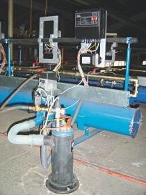
The currently installed burners in the tunnel kiln and the newly developed burners from Kueppers Solutions were tested on an industrial scale at the pilot plant (MeTA) which belongs to the BFI. The pilot plant is specially designed to operate in industrial-like conditions rather than laboratory conditions. Burners with a thermal output up to 1 MW can be tested. Traversing measurements were carried out for the temperature and composition of furnace atmosphere within and close to the flame. Traversing was carried out along the burner axis and at several positions perpendicular to it. The measurement results show the suitability of the burners in various operating conditions for use in a tunnel kiln and are used to validate numerical simulations.
For operation with natural gas, the existing burners show a flame that extends far into the combustion chamber. Combustion mainly takes place outside the burner. When H2 is added, the flame moves into the flame tube, which already glows strongly at a ratio of 20 % H2 by volume. The burner outlet is thermally highly stressed when H2 is added, as can be seen by the glowing of the flame tube in »Figure 3 on the top-right. Pictures taken with a UV-camera reveal the flame shape which cannot be seen on the pictures taken with a camera for visible range. The need to develop a different design that is suitable for higher H2 content is obvious.
The photos in »Figure 4 show that the flame of the burner from Kueppers Solutions is longer than that of the existing burner when operating with natural gas in a cold environment. The UV-images show that the new burner produces a long, slender flame that extends far into the combustion chamber, in comparison to the wider flame of the existing burner. The new burner shows stable flame patterns for hydrogen content from 0 to 100 % of H2. At nominal load and an air-fuel equivalence ratio of 1.05, there is no significant increase in temperature at the burner mouth during the tests at the pilot plant.
3.2 Numerical Simulations
High-speed burners and lance burners are typically used in kilns for firing bricks and tiles. The high impulse due to the high velocity at the outlet of the burner creates a turbulent flow between the setting and achieves uniform heating across the stack’s height and width.
The existing burner was simulated with natural gas and the new one with natural gas and H2. For the simulations, a 3D model of the burners installed in the pilot plant was used. Simulations were carried out in Ansys Fluent as a steady RANS simulation with the k-ε turbulence model. The laminar-flamelet model with a detailed GRI-MECH 3.0 reaction mechanism was chosen for chemical reactions.
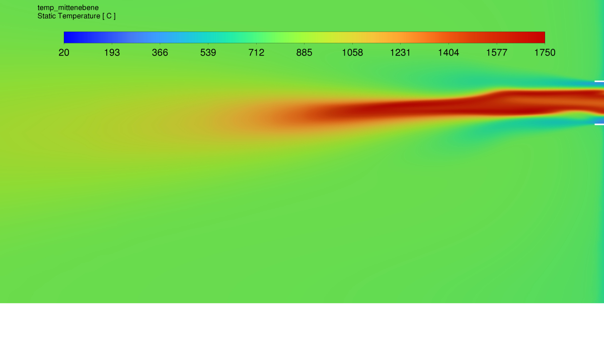
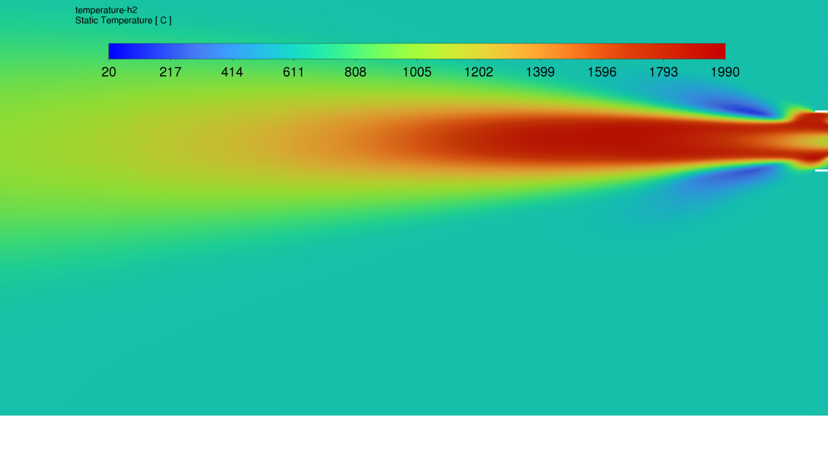
Temperature contour plots are shown below for the two different burner designs. In »Figure 5, results for the existing burner shows a strong and compared to the new burner a slightly shorter flame (»Figure 6). Higher temperatures are reached with the new burner.
In »Figure 7, the temperature profile of the new burner operating with 100 % H2 is shown. The length of the flame is similar to natural gas but the width of the flame increases. This can be explained by the different fuel injection at the swirl unit. Natural gas is injected completely in radial direction. Intensive reaction with combustion air lowers the swirl, H2 is injected mainly in axial direction in the burner axis with high speed. Combustion air reaches tube exit with higher swirl and widens the flame when entering the furnace. Higher temperatures are reached at H2 operation.
4. Simulations of the tunnel kiln
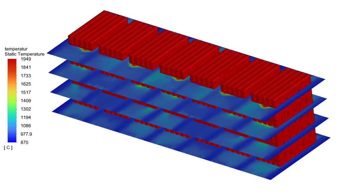
To assess the general flow conditions in the tunnel kiln, simulations with both burners were carried out for a section of the tunnel kiln. For the analysis of the simulation results only the last row and the flow field in the upstream gap is chosen. »Figure 8 shows the 3D model of the tunnel kiln.
Results from the simulations of the tunnel kiln can be seen in »Figures 9 - 11. In the existing configuration, the positions of the burners can be recognized by the hot areas. The areas with higher temperatures are relatively narrow at the top level of the stacks and widen towards the bottom. Due to the flow conditions between the stacks, hot streams are forced into the chan-nels between the stacks, which leads to an uneven temperature distribution across all stacks. The primary flow in the kiln deflects the hot jet from the burner into the channels between the stacks of bricks.
When using the new burner with natural gas, there are also hot zones in the upper area. The temperature distribution is more homogeneous overall. When using hydrogen, there are hot zones in the upper area. Some stacks are more affected by the high temperatures than others, but the positions of the burners change from section to section. In the end, the same conditions will be present in all stacks.
5. Influence on the Product Quality
An important quality criterion, especially for bricks and roof tiles, is the visual appearance, which is influenced by the kiln atmosphere. Test firings for selected brick products with natural gas, pure H2 and blends of natural gas and H2 were carried out on laboratory kilns at IZF with downscaled burners of a new design. »Figure 12 shows the fired clinker bricks in different gas mixtures. No significant colour changes can be observed or measured with a spectrophotometer. There are also no significant changes in the material properties, such as overall shrinkage, firing loss, water absorption, bulk density, and compressive strength.
6. Conclusion
In the presented research project, the use of hydrogen as a substitute for natural gas in the brick and tile industry was investigated. The existing burner of a tunnel kiln was replaced by a dual fuel burner from Kueppers Solutions that can be operated with both natural gas and hydrogen. Experimental tests at the BFI’s test facility and simulations show that the burner from Kueppers Solutions is suitable for use in the tunnel kiln. Test firings in the test kiln at IZF show that the use of hydrogen as a fuel gas has no effect on product quality.
Even if hydrogen will not be available in the necessary quantities in the near future, it is important for brick producers such as project partner Hagemeister GmbH & Co. KG to know whether alternative fuels such as hydrogen are suitable for use in the kiln for economic and ecological reasons. Dual-fuel burners such as the one tested here from Kueppers Solutions can be the solution for the transition from fossil to green fuel gases and offer the necessary flexibility.
Funding
The research project was carried out by VDEh-Betriebsforsch-ungsinstitut GmbH (BFI) and Institut für Ziegelforschung Essen e.V. (IZF) in cooperation with Hagemeister GmbH & Co. KG, Kueppers Solutions GmbH and Keller HCW GmbH. It was funded by the state government of North Rhine-Westphalia.
Acknowledgement
The authors would like to thank the funding organization and the project partners from Hagemeister GmbH & Co. KG, Kueppers Solutions GmbH as well as Keller HCW GmbH for their support of the project.