Improving energy efficiency with the use of hot cooling air in a new combustion concept
 Photo/Foto: IZF
 Photo/Foto: GWI
 Photo/Foto: Lingl
 Photo/Foto: GWI
 Photo/Foto: GWI
 Photo/Foto: GWI
 Photo/Foto: GWI
 Photo/Foto: GWI
 Photo/Foto: GWI
 Photo/Foto: GWI
 Photo/Foto: GWI
 Photo/Foto: GWI
 Photo/Foto: GWI
 Photo/Foto: GWI
 Photo/Foto: IZF
 Photo/Foto: IZF
 Photo/Foto: GWI
 Photo/Foto: GWI
 Photo/Foto: GWI
 Photo/Foto: IZF
 Photo/Foto: GWI
 Photo/Foto: GWI
 Photo/Foto: GWI
 Photo/Foto: GWI
 Photo/Foto: GWI
 Photo/Foto: IZF
 Photo/Foto: Lingl
 Photo/Foto: Bellenberg Brick Plant
In a collaborative project between the Gas-Wärmeinstitut (GWI – Gas and Thermal Research Institute), the Institut für Ziegelforschung (IZF – Brick and Tile Research Institute), the company Lingl and Bellenberg Brickworks (ZWB) financed by Germany’s Federal Ministry for Economic Affairs and Energy as part of the 7th Energy Research Programme, a burner has been developed for tunnel kilns. This directly uses the hot air from the cooling zone as combustion air without the need to make any costly modifications to the exterior of the kiln.
1 Starting situation and background
In the clay brick and tile industry, modern tunnel kilns achieve the process control necessary to handle high capacities and obtain consistent product qualities especially because of the fact that almost over the entire preheating zone as well as the soaking zone they are fitted with burners that not only generate the process heat specifically where it is needed, but at the same time generate an impulse flow with a far reach. As a result, besides the required combustion gas temperature, adequate homogenization of the temperatures and gas compositions is achieved over the kiln cross-section. The precondition for this is that the kiln atmosphere in the preheating and soaking zone is generated largely by the combustion products of generally superstoichiometrically-operated burners, that is they are operated with excess air. The use of the hot air originating in the cooling zone is therefore currently limited to drying of green products as the preheating and soaking zone of the tunnel kiln is only able to utilize this energetically high-value cooling air to a limited extent for the above-mentioned reasons.
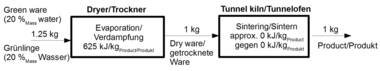
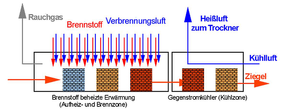
In the tunnel kilns used in the brick and tile industry today, in terms of process engineering, there is a coupling of two subprocesses that take place after each other, as shown in »1. The first part consists of the preheating process up to the soaking temperature, at which temperature equalization takes place within the product setting or in the case of single-tier firing within the green bricks. In addition, for ceramic-engineering-related reasons, a dwell time at this maximum temperature may be necessary under certain circumstances. Following on from this, in the second sub-process the bricks are cooled to exit temperature in a single- or multistage counterflow cooler. The cooling air heated here is removed from the kiln process and used elsewhere for drying of the green brick products [1].
In this way, today’s tunnel kiln differs from earlier tunnel kiln concepts in that in the tunnel kiln there is no explicit firing zone with preceding counterflow preheating of the green bricks, instead there is – more or less – a heating of the fuel in the entire preheating and equalization zone, which may be supported by atmosphere circulating systems.
With this procedure, there is the necessity for maximum synchronization of kiln and dryer operation so that energy optimization of the individual processes becomes almost impossible.
Another aspect that makes the energy coupling between dryer and kiln more difficult is the situation that the kiln works continuously over seven days, 24 hours a day, the dryer on the other hand only during production time in the week so that under some circumstances no continuous utilization of the network energy from the kiln can be guaranteed.
Very extreme is the situation in the roofing tile plants as here the products are fired individually in H setters. This means that in the kiln only around 45 % product is heat-treated while the setters also have to be heated or cooled. For this reason, in these plants more than twice as much energy from the kiln is available than is needed for drying products. For the production of these products, it is all the more important to keep as much cooling air as possible in the kiln.
For the energy optimization of the process for the production of brickworks products, it is necessary therefore to break down the so far tight energy coupling between the cooling zone of the tunnel kiln and the dryer to the largest possible extent. For this, according to the state of the art, it is especially logical to use the cooling air heated during product cooling in the burners of the tunnel kiln as preheated combustion air. This is done with the exclusive aim of fuel substitution with the use of preheated combustion air, that is with the intention to maintain the combustion gases formed in the burner at largely constant quantity and quality and without any notable change to the theoretical combustion temperature.
For the firing of bricks, it is not interesting to effect higher combustion temperatures with preheated air, it is exclusively about reducing the energy demand with otherwise constant conditions even if an increased air factor has to be accepted.
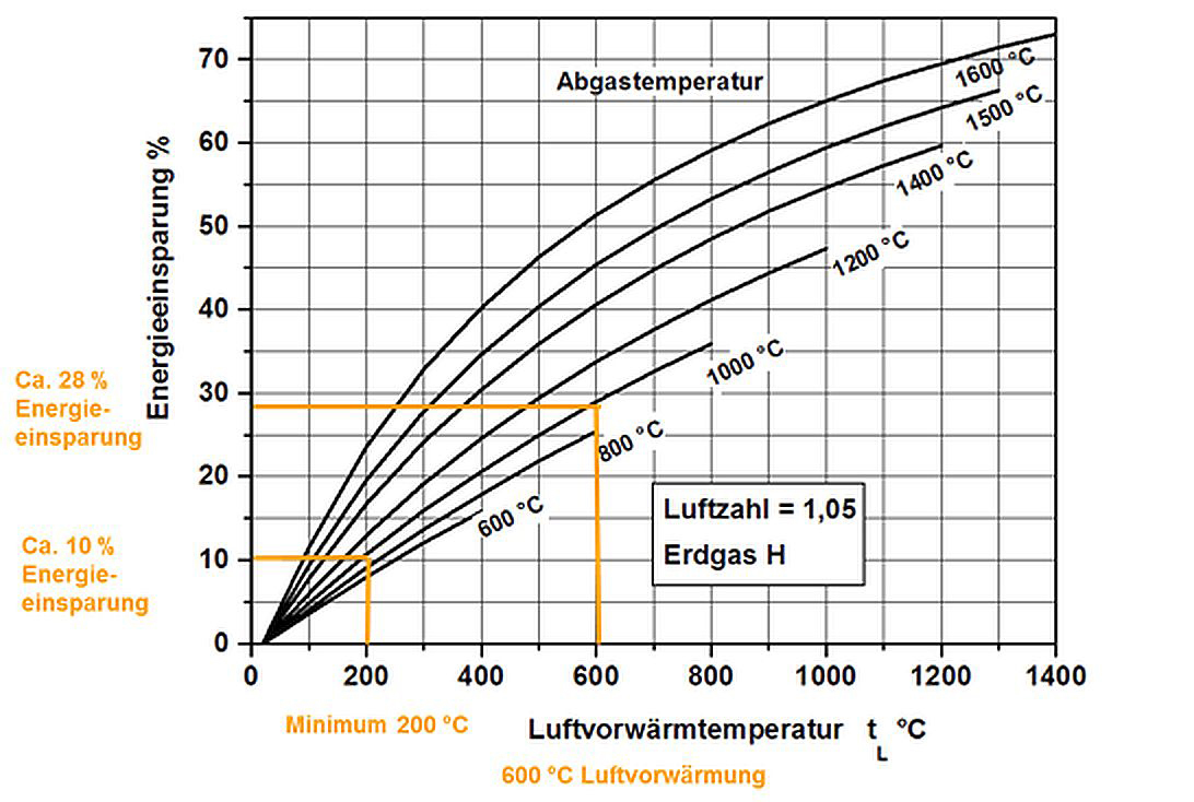
»2 shows the influence of the combustion air temperature on the energy saving resulting from a combustion calculation. In this, the possible percentual energy saving can be seen as a function of the air preheating temperature for various exhaust temperatures. For the diagram, the air ratio and the exhaust gas temperature can be regarded as constant. The energy saving results from the increase in the thermal energy from the air supplied. In the cooling zone, this thermal energy is transferred as a result of the cooling of the bricks to the cooling air and utilized as preheated air.
As obstacles to the use of preheated combustion air technology, the following arguments are raised:
Higher NOx emissions on account of the hotter flame
Space requirement and expense for the insulation of pipelines
Increasing pressure loss and accordingly possibly larger fan necessary
Fan, burners, flame monitoring and valves have to withstand the higher temperatures.
All these arguments do not apply in the utilization of hot air from the cooling zone.
2 New burner concept
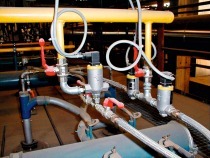
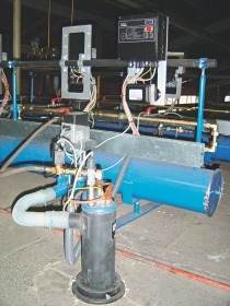
The new burner concept developed in the scope of this project is based on synchronized operation. The fuel is not oxidized with a dedicated air supply but by means of the extraction of the oxidizer already present in the firing chamber in the form of hot air from the cooling zone into the reaction zone. The high gas impulse necessary for this is generated by a high-velocity gas nozzle which feeds combustion gas in cycles into the hot kiln atmosphere zone. The gas nozzle is supplemented with a mixing pipe. »3 shows the prototype of the burner.
Objective of the operating principle is two-stage oxidation of the fuel. The first stage takes place between the gas nozzle and mixing pipe, the second stage at the exit out of mixing pipe. With the high gas impulse, a partial oxidation of the fuel is to be achieved in the first stage. With the mixing of the oxidizer (air) and the fuel in the mixing pipe, the mass flow increases considerably compared with the pure flow of the fuel. At the exit to the mixing pipe, the gas/air mixture should on account of the high impulse extract the necessary combustion air by suction and be completely oxidized.
The development of a novel pure gas injector burner (design and flow calculation) was performed based on CFD simulations (CFD: Computational Fluid Dynamics). Flow and combustion simulations were used in the burner design and development as parameter studies and a flow-related optimization of various geometry models could be performed even before the actual fabrication of the component. The objective of the simulations was to compare the combustion processes of the individual burner models in a simulation domain, which is based on a brick kiln with regard to its atmosphere, temperature and flow velocities.
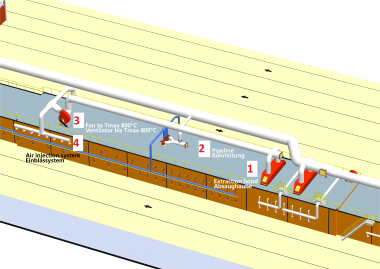
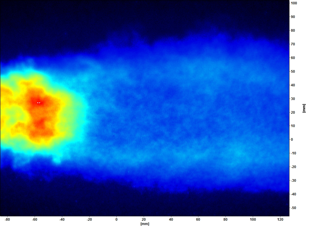
The first numerical visualization of the burner principle is performed by means of a simple combination of a gas lance with an injector nozzle at the exit as well as a free-standing mixing pipe. The simulation domain is characterized in the first step in that an individual burner is supplied with preheated air through a gap and fires into a rectangular firing chamber. »4 shows the flow lines of the air in the firing operation based on the volume fraction of oxygen and shows the suction performance of the combustion gas compared to the hot air.
The simulations show that in cycled firing process with the existing configuration with a two-stage injection effect of the burner sufficient air can be suctioned off for a fully formed flame. From the diagram of the flow lines, it can also be understood that in the area of the injector nozzle because of the high flow velocity of the combustion gas, part of the air is drawn in and at the exit of the mixing pipe because of the high impulse of the fuel/air mix, another part of the air enters into the firing slot.
The firing chamber was based geometrically on a segment between two stacks of bricks in which the burner fires from the kiln roof downwards and is oxidized by an air- exhaust gas flow from the side, cf. »5.
The combustion gas is pressure-controlled and is jetted with ambient temperature into the firing chamber. As the inlet pressure, the pressure levels 0.9 bar (industrial standard) and 1.4 bar (line pressure at Bellenberg Brickworks) were planned. Natural gas H is used as combustion gas.
As oxidizer, an exhaust gas-air mixture (gas composition in the firing zone) is used, as was typically measured in the kiln atmosphere as part of a measurement campaign in the plant, cf. Table 1. This is streamed into the firing chamber with a temperature of 850 °C and at a velocity of 5 m/s. The oxidizer temperature is also based on the measured values. The oxidizer inlet velocity is an empirical value of the research partners.
2.1 Simulation results for a pressure of 1.4 bar
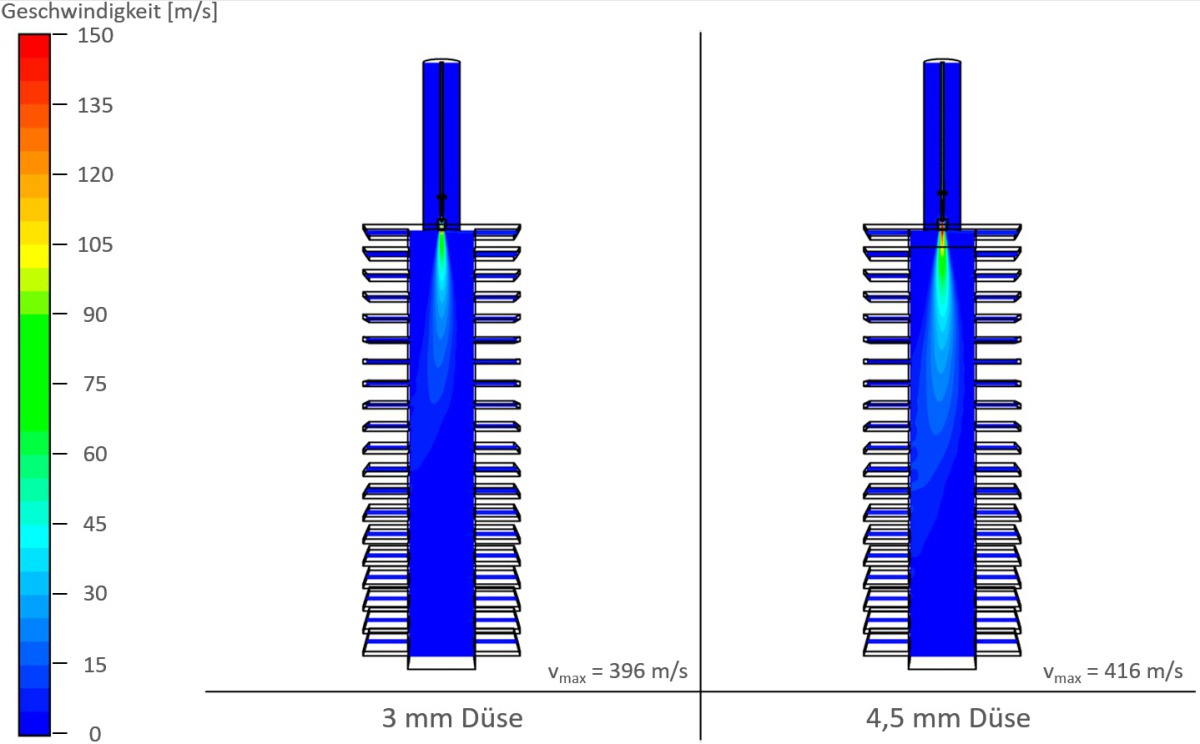
To reproduce the installation at Bellenberg Brickworks, simulations of the burner were performed with a gas inlet pressure of 1.4 bar. Thanks to the pressure-controlled injection of the fuel, a stationary burner output of 112 kW at 3-mm nozzle diameter and 261 kW at 4.5-mm nozzle diameter were achieved. This burner output would correspond to a steady injection of fuel. In the real installation case, however, the burner is operated in cycles with a cycle time up to 1 s. This is followed by a break of several seconds, as a result of which the average burner output falls considerably.
On account of the narrow nozzle cross-sections and the high inlet pressure, the high maximum velocities of around 500 m/s are generated shortly after exit from the nozzle, cf. »6. The figure shows the contour of the velocity distribution from 0 – 150 m/s in a vertical plane along the direction of flow. It can be seen that the stream leaving the burner maintains its impulse over a large part of the firing chamber height and is only influenced to a small extent by the oxidizer flowing from the side. This is conducive to the objective of the maximized penetration of the firing chamber and maximized circulation of the stream.
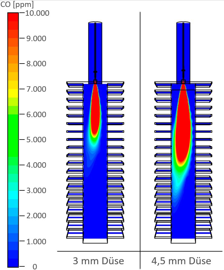
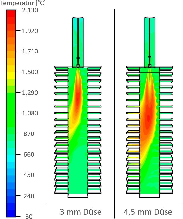
The high impulse of the gas lance is reflected also in the flame contour as well as the temperature distribution in the above-mentioned cross-section, cf. »7. The figure shows the estimated flame contour on the basis of the carbon monoxide distribution in an interval of 0 – 10 000 ppm (dry) and the temperature distribution in an interval of 30 – 2130 °C.
In the diagrams, based on the CO contour it can be seen that the flame – especially with the nozzle cross-section of 4.5 mm – reaches well into the firing chamber. The temperature distribution also shows that hot exhaust gas flows through a large part of the left exit area. For the operation in a brick kiln, this means that bricks can be heated almost over the entire height of around 2 m by means of the novel burner.
2.2 Simulation results for a pressure of 0.9 bar
As for the simulations with a gas pressure of 1.4 bar, numerical calculations were performed with a gas pressure of 0.9 bar. As not all industrial buyers have a gas pressure of 1.4 bar available, the functionality of the principle is checked at a lower gas pressure. In the experience of the research partners, the gas pressure of 0.9 is an industrial standard.
On account of the reduced gas pressure, the stationary burner output falls. For the nozzle diameter of 3 mm or 4.5 mm, an output of 87 kW or 206 kW respectively is obtained. This corresponds to an around 21-% reduced stationary burner output compared to the gas pressure of 1.4 bar. Like the falling output values, the maximum flow velocities also fall, cf. »8. For both nozzle cross-sections, the maximum velocities fall to a level of around 400 m/s. This corresponds to a reduced velocity of around 18 % compared to the values at higher gas pressure. In addition, it can be seen from the velocity curve that the flow velocities in the firing chamber decline faster.
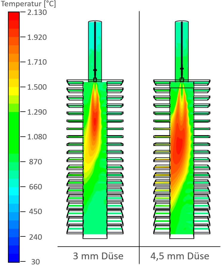
In »9 the flame contours and temperature distribution are shown based on the dry CO volume share on a scale from 0 – 10 000 ppm and the temperature distribution on a scale from 30 – 2130 °C. From the figures it can be seen that, like at the gas pressure of 1.4 bar, a high penetration of the firing chamber is achieved by the flame, especially with the 4.5-mm nozzle. As a result, bricks can be heated over almost the entire stack height. The new burner concept does not appear very sensitive to reduced gas pressure.
From the CFD simulations it can therefore be seen that injection principle basically functions for various pressure levels and nozzle cross-sections. Both a partial oxidation in the mixing pipe and a full fuel oxidation in the firing chamber can be achieved. Especially for the nozzle cross-section of 4.5 mm, from the numerical simulations a high penetration depth of the flame and the hot exhaust gas into the firing chamber can be achieved both at a gas pressure of 0.9 bar and 1.4 bar.
On the basis of the initial considerations and the simulations of a wide range of geometries, a test burner was developed for trials at GWI and IZF.
As a basis for the development of a test burner, the Lingl pure gas burner was used. For the fabrication of the test burner, first the SiC nozzle is removed. To replace this, heat-resistant steel is used. The design of the burner consisted mainly of a jet nozzle with two different diameters and a burner hood with a diameter matched to the nozzle cross-section for the generation of a two-stage injection effect. The basis for dimensioning of the various parameters are predominantly the results obtained in the numerical simulation. As the significant values for the operating principle, the parameters jet nozzle diameter, mixing pipe/injector hood diameter and distance of the jet nozzle to the mixing pipe. So that the specific influence on the operation can be determined, these can be adjusted on the test burner or the corresponding components can be easily changed. Accordingly, simple adjustment of the different combinations in test operation is guaranteed. Special feature of this burner is that the burner is equipped with an external purging air connection. The purging air is designed to prevent coking of the small diameter at the burner muzzle. The purging air is only supplied during the break in operation. To ensure trouble-free ignition, pure gas burners should only be used in a temperature range > 750 °C as they are not equipped with ignition monitoring.
3 Surveying of the tunnel kiln
To assess the efficiency of the newly developed burners in real operation of the tunnel kiln, the kiln is first surveyed in its original state. With the repeat of such an operational measurement after conversion with the newly developed burners, with the measured data obtained before and after, a comparison is possible, which provides information about the influence of the modified burner technology on the kiln operation.
3.1 Measurements in the kiln in its original condition
For recording of the original condition, measurement of the harmful substances CO, CO2, NOx and O2 and the temperatures in the firing chamber was conducted. For this purpose, measurements were conducted on a total of eleven rows of burners with different brick setting.
For the measurement of the exhaust gas emissions, a water-cooled suction pyrometer was used. Sampling was performed in the openings of the installed gas burners, the individual burners being dismantled for the measurements and a vertical grid of the kiln chamber measured.
At the same time, the firing curves were measured, and energy balances drawn up to determine the influences of the new burners here, too.
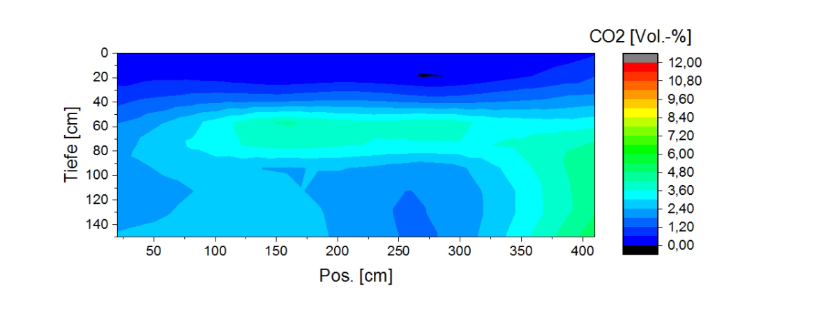
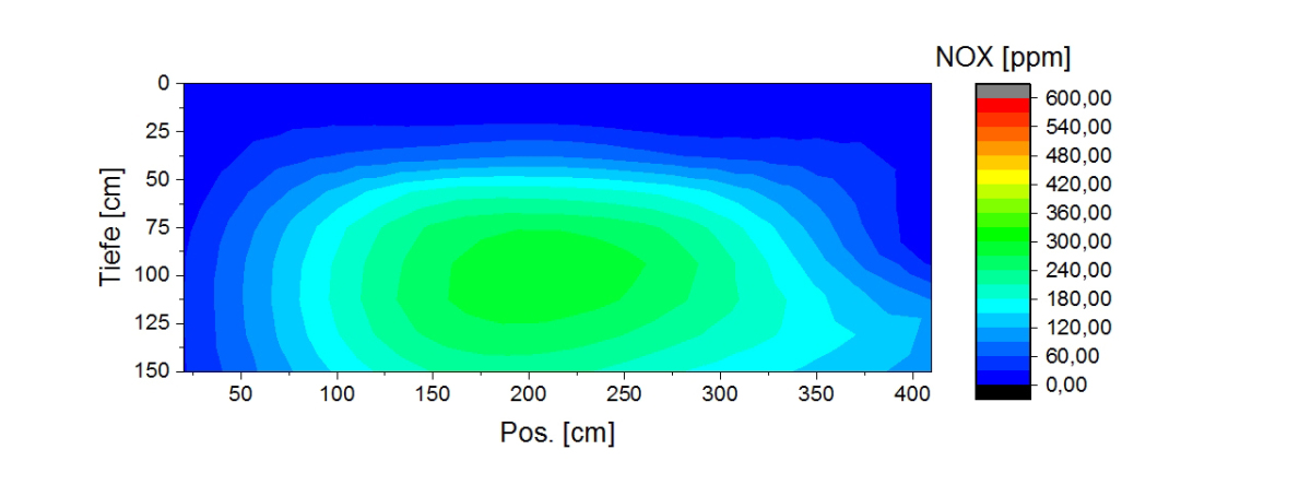
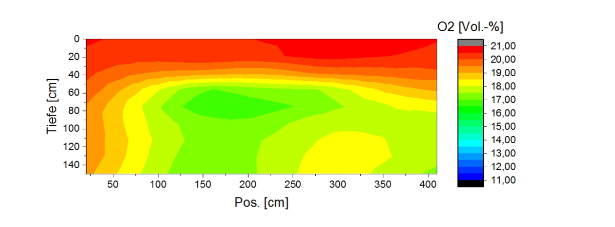
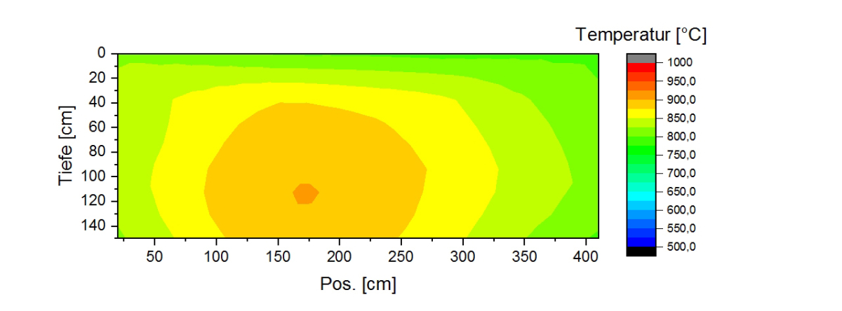
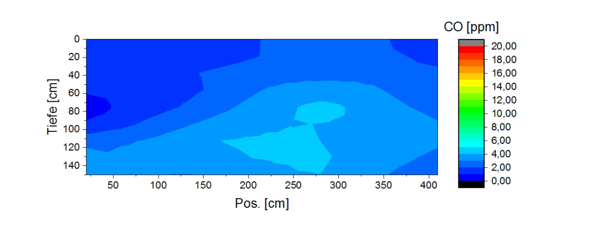
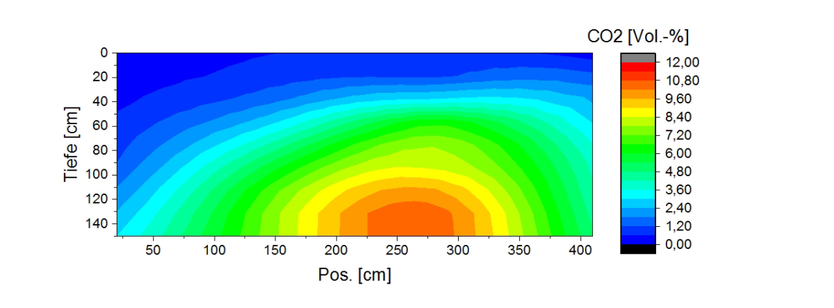
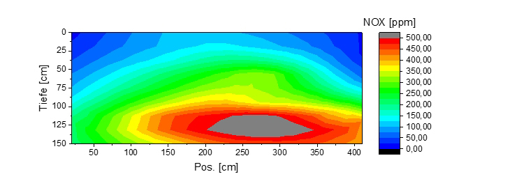
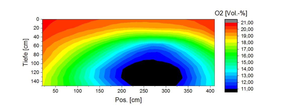
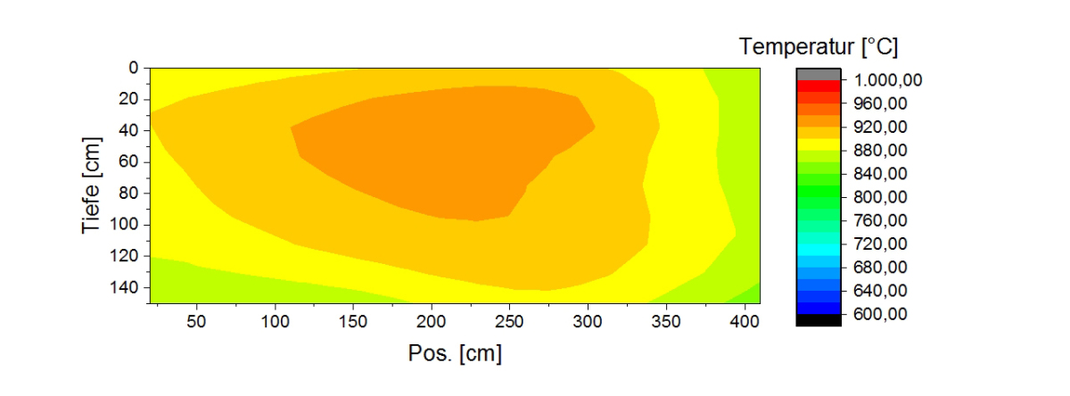
With the pollutant and temperature measurements, conclusions can be drawn with regard to the distribution of the values recorded on a burner level. »10 to 14 show as an example the recorded vales for the burner row 13 and the temperature distribution along the firing zone. The measurement depth in the firing chamber is shown on the y-axis while the width of the firing chamber is plotted on the x-axis.
From »14 it is clear that the temperatures extend over an interval from 750 °C to around 950 °C. In the centre of the kiln cross-section there are higher temperatures than in the boundary areas. This is accompanied by higher NOx concentrations and a lower oxygen content in the central zone, cf. »12 and »13. In respect of the concentrations of CO2, NOx, and O2, a lateral asymmetry can be determined, higher values being determined on the right boundary. In addition, there is an area with low temperature and low emissions overall near the kiln roof. This is ostensibly attributed to differing flow conditions between the brick stacks and the kiln roof or the gaps at the edges.
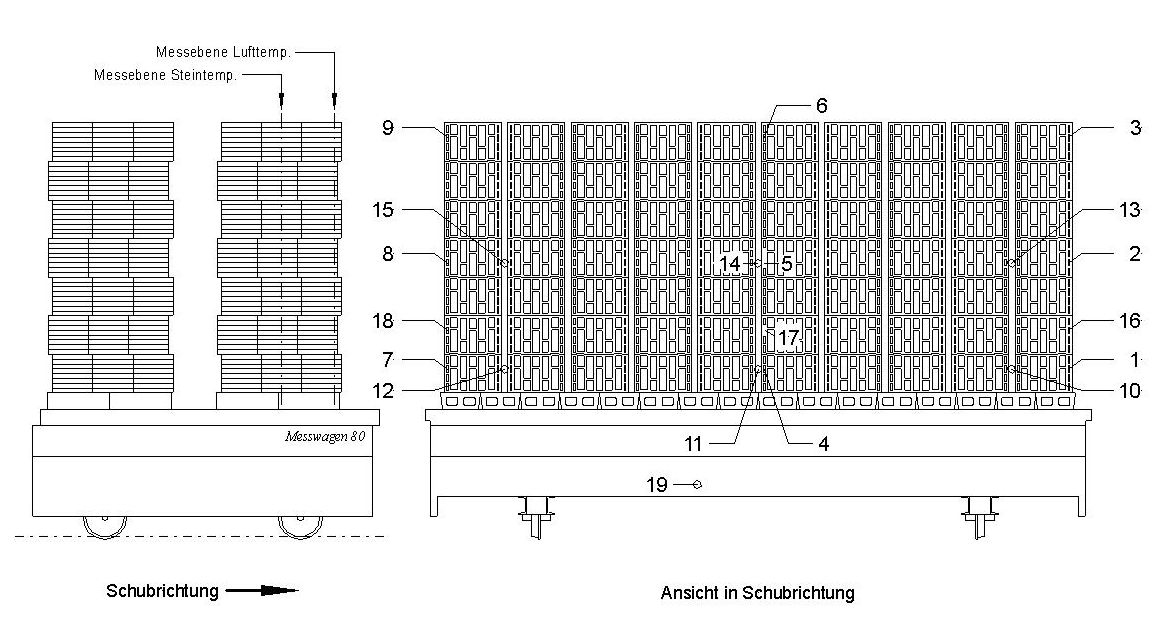
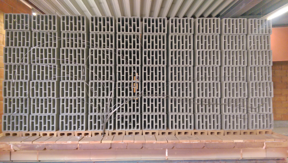
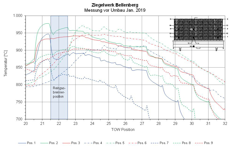
For the measurement of the firing curves, the setting on a tunnel kiln car was fitted with thermocouples to record the setting and air/gas temperatures depending on the location and time during the travel through the kiln. An example of the arrangement of the thermocouples on the kiln car is shown in »15.
At the same time, with the measurement of the firing curves, all volumes of air and gas necessary for assessment of the process and the energetics were recorded.
4 Measurements at the GWI
To assess the flame pattern and the emission behaviour of the newly developed burner was, at the same time as the measurements on the original tunnel kiln a single burner fabricated from steel was tested in measurements at a GWI test kiln. On the test kiln used for the experimental tests at the GWI there are a total of seven closable openings at the mid-level of the kiln that allow direct access to the firing chamber during operation. In addition, a relatively large viewing window in the front section of the kiln can be opened, permitting the application of optical methods to make visible and measure the burner flames.
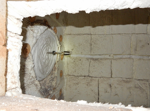
For the tests, the test burner is mounted on the front of the test kiln. On account of the comparatively small outer diameter of the burner, the remaining space in the connecting opening of the kiln was lined with fibre material. In the finished installation state, the muzzle of the test burner projects around 20 cm deep into the interior of the kiln. »17 shows a view of the installed burner through the viewing window at the side.
In the lower output range of the burner, heating of the firing chamber by means of gas-operated steel radiant tubes is necessary as the thermal energy released by the individual burner is not sufficient to heat the kiln chamber to the target temperature range from 750 to 850 °C. On account of the burner design without ignition system and pilot flame, a temperature ³ 750 °C is necessary to guarantee self-ignition of the mixture. The volume flow of combustion air introduced into the firing chamber was around 325 mn³/h at all operating points.
In the measurement of the kiln atmosphere without burner operation in Test No. 1, only a low contamination with CO2 and CO was shown owing to the use of the gas-fired radiant tubes. In the lower load range of the burner, notable CO concentrations can be determined, which, however, from a power output of around 50 kW decline strongly. Nitrogen oxides are practically not present in the entire tested load range. The volume flow of supplied air at around 325 mn³/h leads to a strongly hyperstoichiometric combustion in all load points.
The low NOx emissions of the test burner are based on the flameless combustion. At almost all operating points, no visible flame was formed, the high firing gas impulse led to a strong mixing and dilution of the reaction zone. In connection with the kiln chamber temperature of ³ 750 °C, no stable visible flame could form, and the combustion gas was oxidized without a flame, Only in the output range from 40 to 50 kW and 80 kW, at a certain distance from the muzzle, an unstable flame was formed, which changed its position frequently and erratically along the burner axis. »18 and »19 show the flame at a power of 45 kW as a digital photo and OH image.
A compact, cloud-shaped flame can be seen, which shows a clearly defined main reaction zone and a downstream reaction zone of weaker intensity. The temperature in the flame is much higher compared to flameless combustion, which is why increased thermal nitrogen oxides are formed. This explains the measured peak concentration of 137 mg/mn³ppm in Test no. 5.
The wide output range from 20 to 100 kW is a big advantage for the use in a tunnel kiln. The predominantly flameless combustion and the low emission behaviour in respect of NOx are also very positive. Other tests showed that the combustion appears to be very stable to external influences (fluctuating O2 content).
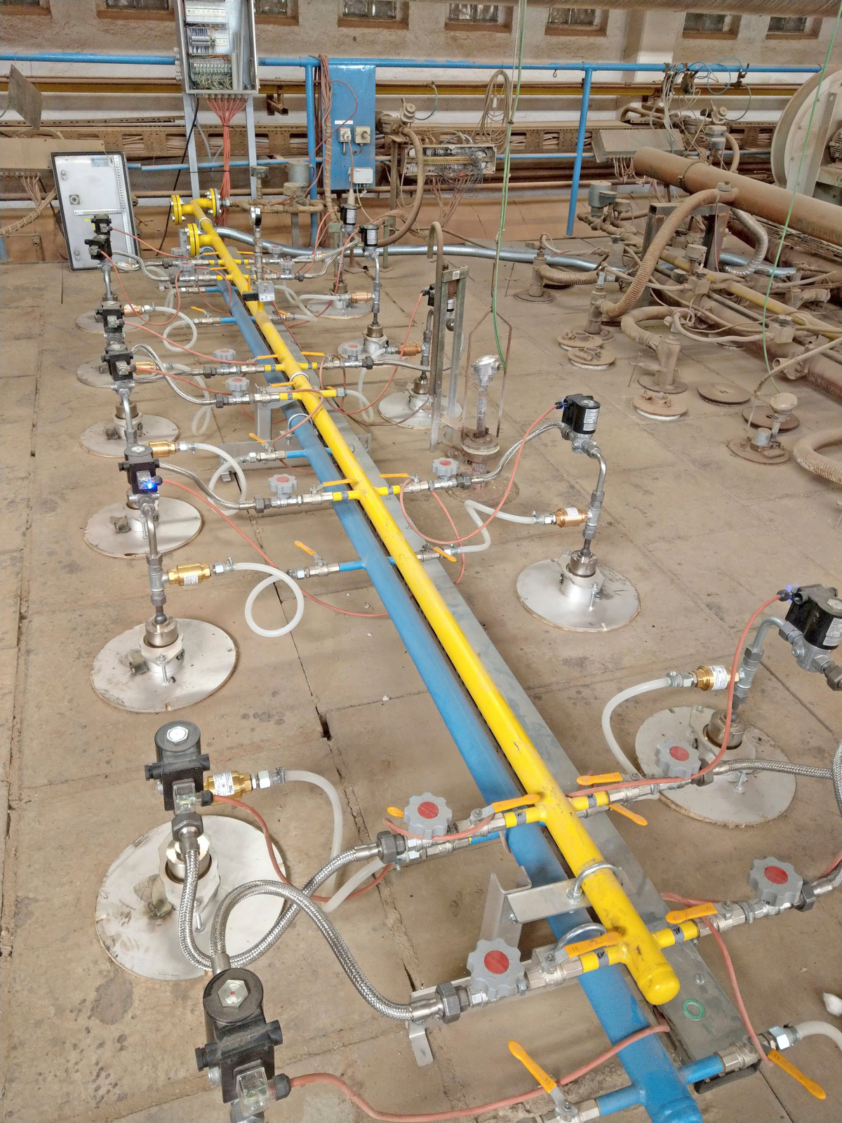
5 Integration of a burner group with the new burner in the installed tunnel kiln
Based on the design of the test burners, for the selected kiln at Bellenberg Brickworks, first an entire burner group with burner lances was fabricated from high-temperature steel. This group comprises 13 burners with a theoretical output of 100 kW each for a specified gas pressure of 1.4 bar.
The group consists of the 13 above-mentioned burners, a group gas pipeline, and a purging air pipeline. The group gas pipeline is supplied via the central gas pipeline. An already installed gas magnetic valve in the central gas pipeline enables or closes the gas supply to the entire group. Every burner is allocated on the gas side a ball valve, metering valve, magnetic gas valve and a check valve. The air supply is only used for purging of the injector lance and is insignificant with regard to combustion. The supply with purging air comes from a neighbouring HV burner group. The air consumption is only marginal. The purging air for each burner can be shut off with a ball valve.
With regard to the control and regulation technology, it was necessary to make any modifications. The cycling is based on the sequence similar to that to the old burner group and therefore no essential change is made compared to the previous concept.
6 Examination of the tunnel kiln after conversion to injector burner
To determine possible differences after changing of the burner installation, following conclusion of the conversion, the tunnel is re-examined according to the procedure in the previous measurement campaigns. An overview of the measured data is shown in »21 to »25.
The oxygen content in the measured section has fallen substantially especially in the centre, high O2 concentrations are present only in the upper boundary areas. Associated with the temperature rise and the lesser dilution of the exhaust gas with air, especially in the middle of the measured area, the nitrogen oxide concentrations increased. The relevant NOx concentration of the kiln overall, however, still lies below the permissible limit.
The measured percentage of the CO2 has increased overall on account of the lesser dilution of the combustion gases. Carbon monoxide is present only in concentrations in single-figure volume percentage range thanks to the good burnout.
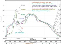
At the same time as the measurement of the kiln atmosphere by the GWI, the IZF measured the firing curves on the same format as before the conversion. In »26 it can be seen that even this one burner group can effect a homogenization of the temperatures. The three lower temperature curves (dark blue, blue, yellow) show setting positions that at the point in time were not reached sufficiently by the burners. Here a remedy is available by means of adjustment, e.g. based on the gas pressure.
Several measurements were conducted to verify the results and in this period of time the burners initially fabricated from high-temperature-resistant steel were replaced with corresponding burners made of SiC as this material demonstrates clear advantages over the steel models at the service temperatures prevailing in the tunnel kiln. In the various tests conducted by Lingl, the optimum nozzle design was found as shown in »27.
At the same time as the measurements of the firing curves, all air and gas quantities at the equipment necessary for assessment of the process and the energetics were measured. From the results, an energy balance could be compiled in each case.
As an extract from the complete balances, in the following Table 3, the energy consumption based on the use of natural gas is listed. In the plant natural gas H is used with an average calorific value of 36.6 MJ/mN³.
If the energy consumption is analysed before and after the conversion, then a reduction in the specific energy consumption of 15 % can be calculated. Here it should, however, be noted that during the installation of the new burners, other optimizations were performed on the kiln so that the cumulative effect of the measures led to this energy saving. The extent of the saving, however, corresponds with the previously conducted simulations of the firing process.
In Bellenberg Brickworks, with the kiln control system and the connected measurement and control systems, different operating data were recorded. In this context, especially the monthly averaged specific gas-energy consumption should be mentioned. In »28, the records from 2017, 2018 and 2019 can be seen.
From these long-term records, it can also be seen how the installation of burner group with the new pure-gas injector burners has led to a reduction in the specific energy consumption (blue curve). The measured values lie well below those from the years 2017 (red curve) and 2018 (green curve).
As the pure gas injector burners use the hot air in the kiln as preheated combustion air, the amount of combustion air introduced into the kiln could be corrected. Whereas in January 2019, prior to the conversion, 6 240 mN³/h were still supplied for combustion, in January 2020 this figure was just 4 190 mN³/h, without any resulting signs of reduction or sub-stoichiometric combustion.
Besides the values measured by the institutes and the tests, the quality improvement in the products determined by the brickworks as part of the plant’s internal production control should also be mentioned. With the improved homogenization of the kiln atmosphere and temperatures, the quota of broken products, especially from the lower parts of the setting, could be reduced considerably.
7 Recommendation for redesign including design and operating criteria
The Lingl Pure Gas Injector Burner (LRGIB) developed as part of the research has been designed as a top-burner for ceramic kilns and for the use at kiln chamber temperatures above 750 °C on account of the ignition temperature of natural gas and the non-existent ignition monitoring at the burners,. The gas and air are mixed directly after the exit of the flame from the burner. With the special geometric form of the exit nozzle, the hot kiln chamber atmosphere is sucked out of the roof gap as combustion air, mixed with the fuel in the mixing basket and then ignited in the kiln chamber and combusted. The LRGIB works more energy-efficiently that a normal gasifier burner as no cold combustion air has to be supplied to the burner. On account of the high exit velocities at the muzzle of the fuel nozzle, an additional circulation of the kiln chamber atmosphere is generated, and a uniform temperature distribution achieved as a result.
For new kilns, the burner output can be matched to the energy requirement. The number of the burners in a row of stokeholes is oriented to the setting height, the type of setting, the setting structure and the required circulation effect.
The burner group is supplied with gas via the central gas pipeline. The group magnetic gas valve is used to control the gas supply. Every burner is allocated a ball valve, feed valve and separate magnetic gas value for individual burner control. A minimal air supply is used to purge the injector lance and is insignificant with regard to combustion. The installation of the burners on the kiln roof is similar to the installation of the gasifier burners.
The big advantage of these burners is that existing kilns can be upgraded without major modifications, but simply with the replacement of existing burners.