HoTempLa – New Transport System on the Basis of High-Temperature Bearings for More Energy-Efficient Firing of Brickwork Products in Tunnel Kilns


Background
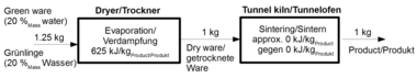
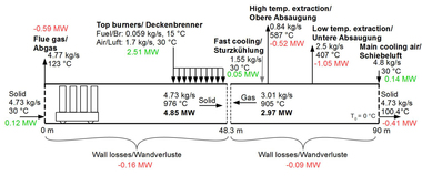
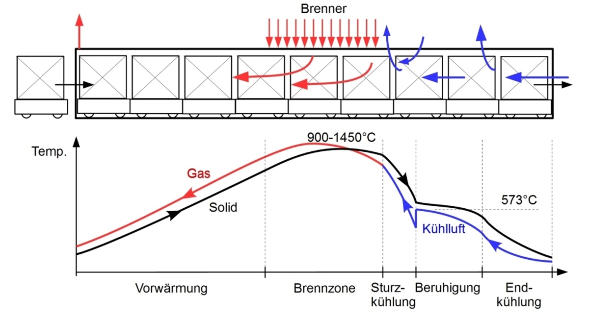
In the ceramics industry, the tunnel kiln is the most commonly used type of kiln for making clay bricks and other ceramic products like stoneware, porcelain and ceramic sanitaryware. A longitudinal section of a tunnel kiln is shown in the schematic in »Fig. 1. The kiln cars with the relevant ware setting are transported through the kiln. In the middle of the kiln is the firing zone. In this zone, a large number of burners are arranged, which supply the thermal energy required. The temperatures in this kiln section reach the maximum and lie slightly above the firing temperature of the ware setting. The hot combustion gases are discharged from the kiln in a counter flow to the brick setting. Heat is transferred between the gas and brick setting so that the brick setting heats up from room temperature to near firing temperature. This zone of the kiln is termed the preheating zone. After the ware setting has left the firing zone, it is first cooled to near the quartz inversion temperature. This is referred to as rapid cooling. The ware passes through the quartz inversion temperature as slowly as possible to prevent material failure. This is shown in the temperature curve as a plateau. Then the bricks are cooled to room temperature with the injection of more air. This zone of the tunnel kiln is termed the final cooling zone.
The mass of the tunnel kiln car is a factor known in the industry to significantly influence the energy required.
According to Hagens [1], the energy actually stored in the tunnel kiln is almost four times the theoretically stored value. This results from the assumption that the temperature profile of the kiln car corresponds to that of the ware along the tunnel kiln. Since the mass of the kiln car and the ware differ by 1.5 times, this actually leads to a different temperature profile. This means that the total energy loss from the kiln car is 6 times the energy loss from the ware. To reduce the energy loss attributed to the kiln car, the mass of the kiln car must be reduced. The lower mass of the tunnel kiln car reduces the heat that is absorbed in the preheating zone of the tunnel kiln, which further increases the thermal efficiency of the tunnel kiln. To lower the exit losses and therefore the energy required, in the scope of this project, tests were conducted to determine how far the kiln car could be replaced with a carrier plate if suitable high-temperature bearings were available.
Construction of the bearing geometry by means of simulation and fabrication
The work began with the derivation of a first stationary 3D model (see »Fig. 2) based on known preliminary works. This model uses the symmetry and periodicity of the total geometry for simplification.
In the model, for the two contact zones (bearing/roller and roller/plate) areas for a local refinement of the discretization (gridding) are included. For the friction coefficient, a value of 0.7 was taken. A load of 100 N is imposed normal to the plate of the sub-model. The results for the first principal stress of this model can be seen in »Fig. 3. The maximum tensile load occurs severely localized at the bearing point between support and roller (24 MPa). The cause of the tensile stress can be identified as the deflection of the roller.
With a parameter study, the dimensions of the bearing were determined. The dimensions of the bearing are shown in »Fig. 4.
Fabrication of the components followed the classical powder technology route. From press granulate, blanks were produced by means of cold isostatic pressing of cylinder rollers (for bearing rollers) and blocks (for bearing blocks). The blanks are milled in the green state to near-net shape (CNC-5-axis-machining centre). This was followed by thermal debinding to burn out the organic binder. The debinded parts were sintered in a gas pressure sintering furnace. The density determined based on the Archimedes principle and the open porosity of the components measure 3.24 g/cm³ and < 0.05 % respectively. »Fig. 5 shows the sintered bearing block with roller.
Tests with the ceramic bearings
»Fig. 6 shows the kiln with the necessary components for conducting the experiments. »Fig. 6 b shows the pushing rod outside the kiln and »Fig. 6 c shows the inside of the kiln with the pushing rod. The thermocouples that measure the temperature on the outside and inside of the bearing are indicated with 1 and 2 and shown in »Fig. 6 d. The bearings were fixed to the bottom plate with two pins made of heat-resistant steel in each case.
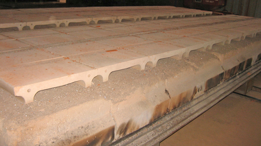
»Fig. 7 a shows the carrier plate with the load on the rollers. There is a total of six rollers: three on each side. The carrier plate lies direct on the surface of the rollers (»Fig. 7 b). The behaviour of the rollers during pushing and pulling of the carrier plate was recorded, and photos in »Fig. 8 show the rotation of the outside rollers when the carrier plate moves on the rollers. »Fig. 8 a shows the starting position of the carrier plate and, to indicate the rotation of the rollers, the roller and the block have been marked. »Fig. 8 b shows the rotation of the rollers when the carrier plate is moved to and fro in intervals, »Fig. 8 c. The rolling motion of the bearings in the cold state was not optimal.
A heating rate of 100 K/h was realized. From a bearing temperature of 800 °C, pushing of the plate was started. Within the duration of one test, around 1 000 – 1 400 pushes were realized (»Fig. 9). After each test, the set-up and bearing were tested for damage in order to evaluate this and eliminate any impediments in the test procedure.
Evaluation
The movement of the shaft in the bearing lining generates wear over the entire test duration. The wear particles collect at the shaft and are distributed over the entire bearing block (»Fig. 10 b). This abrasion and the grooves formed on the bearing lining and shaft (»Fig. 10 c) were investigated and analysed by the IKTS. The examination of the abrasion by means of XRD did not yield any useful results. Obviously, the percentage of amorphous phase was predominant. For that reason, the abrasion was more closely examined by means of scanning electron microscopy with EDX. Different spectra were captured. Mainly the element Si as well as smaller percentages of Al, Y, O, and N were detected, which are the (main) constituents of the Si3N4 ceramic, »Fig. 11. Metallic abrasion was only found as isolated traces. For that reason, the wear was attributed mainly to the ceramic.
A hoped-for significantly positive effect of a self-lubrication based on the formation of SiO2 could not be determined. Nevertheless, positive conclusions could be drawn from the series of tests. The stability and strength of the bearings, tested under laboratory-scale test conditions, could be confirmed. Moreover, in »Fig. 12 it can been seen that the bearings after the series of tests, with real projected load and several heating and cooling phases, exhibit only minor damage not impairing their function.
Simulative comparison of the transport systems
Clinker brick tunnel kiln
The exit energy of the bricks from all tunnel kilns remains the same, which can be attributed to the same mass throughput rate of the bricks. The energy loss caused by the gas and the walls also remains the same in the different tunnel kilns. The energy loss caused by the upper and lower cooling air extraction remains the same in all tunnel kilns, which shows that a reduction of the volume of cooling air is not achieved when the heavy kiln cars are replaced with the carrier plate. The fuel consumption in the tunnel kiln with a carrier plate on the bottom of the tunnel kiln falls by 10 %, while the energy loss through the base rises from 10 kJ/s to 61 kJ/s. For the tunnel kiln in which the carrier plate is positioned on the stationary kiln car, the energy saving is around 12 % and the energy loss through the base 36 kJ/s compared to 10 kJ/s for a tunnel kiln with a normal kiln car as transport system.
The energy saving for a reduction of the conductivity of the carrier plate to 0.1 W/m∙K is 14 % compared with a carrier plate with a conductivity of 1.5 W/m∙K. When a carrier plate with a conductivity of 0.1 W/m∙K is used, the fuel consumption in kilns without stationary kiln cars be reduced by 23 % and in kilns with stationary kiln cars by 25 %.
Roofing tile tunnel kiln
The thermal conductivity of the carrier plate is taken to be 1.5 W/m∙K. In the tunnel kiln with the carrier plate, the energy loss through the upper cooling air extraction increases from 86 kJ/s to 302 kJ/s. This can be attributed to the fact that a high volume of cooling air is necessary to counter the heat that is radiated by the carrier plate to the roofing tile. The energy loss through the upper cooling air extraction also increases when the carrier plate is located on the stationary kiln car. The lower loss increases in the case of with carrier plate and carrier plate on kiln car to 93 kJ/s and 54 kJ/s, respectively. The fuel saving is 3 %, when the transport system is a carrier plate and 4 %, when the carrier plate is positioned on the stationary kiln car.
When the conductivity of the carrier plate is changed to 0.1 W/m∙K, the energy saving achieved is 20 %. If therefore a carrier plate with a conductivity of 0.1 W/m∙K is considered, the fuel consumption can be lowered to 22 %. When the carrier plate is located on the stationary kiln car, the fuel consumption falls by 23 %.
The project was supported by Germany’s Federal Ministry of Economic Affairs and Climate Protection.